Thermistor classification method & symbol identification
The thermistor is a semiconductor ceramic component made of transition metal oxide as the main raw material, and belongs to the category of negative temperature coefficient thermistor. It has the characteristic that the resistance value changes correspondingly with the change of temperature, that is, the resistance value decreases as the temperature rises. By using this feature, when it is connected in series in the power supply loop, the startup surge current can be effectively suppressed. And after the completion of the suppression of the inrush current, the resistance of the power type NTC thermistor is reduced to a very small extent by the continuous action of the current. It can also be used for temperature measurement and metering equipment, temperature compensation in transistor circuits. The thermistor is connected in series in the circuit, mainly for "current insurance".
Classification
In order to avoid the inrush current generated in the electronic circuit at the moment of power-on, a power type NTC thermistor is connected in series in the power supply circuit, which can effectively suppress the inrush current at the time of starting. And after the completion of the suppression of the inrush current, the resistance value of the power type NTC thermistor will drop to a very small extent due to the continuous action of its current. It consumes negligible power and does not affect normal operating current. Therefore, the use of power-type NTC thermistors in the power supply circuit is the easiest and most effective measure to suppress surges during startup to protect electronic equipment from damage.
Thermistors are sensitive components that are developed early, have many types, and are more mature. The thermistor is composed of a semiconducting ceramic material, and the principle of utilization is temperature-induced resistance change. If the electron and hole concentrations are n and p, respectively, and the mobility is μn, μp, then the conductance of the semiconductor is: σ=q(nμn+pμp) Since n, p, μn, and μp are all functions dependent on temperature T. Therefore, the conductance is a function of temperature, so the temperature can be derived from the measured conductance and the resistance-temperature characteristic curve can be made. This is how semiconductor thermistors work. Thermistors include positive temperature coefficient (PTC) and negative temperature coefficient (NTC) thermistors, as well as critical temperature thermistors (CTR).
1. Rated zero power resistor R25 zero power resistor. When the PTC thermistor value is measured at a certain temperature, the power consumption added to the PTC thermistor is extremely low, so that the resistance change of the PTC thermistor caused by its power consumption is negligible. The rated zero power resistance refers to the zero power resistance measured at an ambient temperature of 25 °C.
2, Curie temperature Tc: For PTC thermistor applications, the temperature at which the resistance value begins to increase steeply is important, which we define as the Curie temperature. The resistance of the PTC thermistor corresponding to the Curie temperature RTc = 2*Rmin.
3. Temperature coefficient α: The temperature coefficient of a PTC thermistor is defined as the relative change in resistance due to temperature changes. The greater the temperature coefficient, the more sensitive the PTC thermistor reacts to temperature changes. α = (lgR2-lgR1)/lge(T2-T1)
4, rated voltage VN: The rated voltage is the supply voltage below the maximum operating voltage Vmax. Usually Vmax = VN + 15%
5, breakdown voltage VD: The breakdown voltage is the highest voltage withstand capability of the PTC thermistor. The PTC thermistor will fail breakdown above the breakdown voltage.
6, surface temperature Tsurf: The surface temperature Tsurf refers to the temperature of the surface of the PTC thermistor when the PTC thermistor is in a state of thermal equilibrium with a predetermined voltage and with the surrounding environment for a long time.
Representation symbol of the thermistor in the circuit diagram
Classification
In order to avoid the inrush current generated in the electronic circuit at the moment of power-on, a power type NTC thermistor is connected in series in the power supply circuit, which can effectively suppress the inrush current at the time of starting. And after the completion of the suppression of the inrush current, the resistance value of the power type NTC thermistor will drop to a very small extent due to the continuous action of its current. It consumes negligible power and does not affect normal operating current. Therefore, the use of power-type NTC thermistors in the power supply circuit is the easiest and most effective measure to suppress surges during startup to protect electronic equipment from damage.
Thermistors are sensitive components that are developed early, have many types, and are more mature. The thermistor is composed of a semiconducting ceramic material, and the principle of utilization is temperature-induced resistance change. If the electron and hole concentrations are n and p, respectively, and the mobility is μn, μp, then the conductance of the semiconductor is: σ=q(nμn+pμp) Since n, p, μn, and μp are all functions dependent on temperature T. Therefore, the conductance is a function of temperature, so the temperature can be derived from the measured conductance and the resistance-temperature characteristic curve can be made. This is how semiconductor thermistors work. Thermistors include positive temperature coefficient (PTC) and negative temperature coefficient (NTC) thermistors, as well as critical temperature thermistors (CTR).
1. Rated zero power resistor R25 zero power resistor. When the PTC thermistor value is measured at a certain temperature, the power consumption added to the PTC thermistor is extremely low, so that the resistance change of the PTC thermistor caused by its power consumption is negligible. The rated zero power resistance refers to the zero power resistance measured at an ambient temperature of 25 °C.
2, Curie temperature Tc: For PTC thermistor applications, the temperature at which the resistance value begins to increase steeply is important, which we define as the Curie temperature. The resistance of the PTC thermistor corresponding to the Curie temperature RTc = 2*Rmin.
3. Temperature coefficient α: The temperature coefficient of a PTC thermistor is defined as the relative change in resistance due to temperature changes. The greater the temperature coefficient, the more sensitive the PTC thermistor reacts to temperature changes. α = (lgR2-lgR1)/lge(T2-T1)
4, rated voltage VN: The rated voltage is the supply voltage below the maximum operating voltage Vmax. Usually Vmax = VN + 15%
5, breakdown voltage VD: The breakdown voltage is the highest voltage withstand capability of the PTC thermistor. The PTC thermistor will fail breakdown above the breakdown voltage.
6, surface temperature Tsurf: The surface temperature Tsurf refers to the temperature of the surface of the PTC thermistor when the PTC thermistor is in a state of thermal equilibrium with a predetermined voltage and with the surrounding environment for a long time.
7, the action current Ik: The current flowing through the PTC thermistor is sufficient to cause the PTC thermistor to rise above the Curie temperature, which is called the operating current. The minimum value of the operating current is called the minimum operating current.
8, no action current INk: The current flowing through the PTC thermistor is insufficient to cause the PTC thermistor to rise above the Curie temperature, which is called a non-operating current. The maximum value of the non-operating current is called the maximum non-operating current.
The main features of the thermistor are:
1. High sensitivity. The temperature coefficient of resistance is 10 to 100 times larger than that of metal, and the temperature change of 10-6 ° C can be detected;
2. Wide operating temperature range. Normal temperature devices are suitable for -55 ° C ~ 315 ° C, high temperature devices are suitable for temperatures above 315 ° C (currently up to 2000 ° C), low temperature devices are suitable for -273 ° C ~ 55 ° C;
3. Small size. Ability to measure the temperature of voids, cavities and blood vessels in the body that cannot be measured by other thermometers;
4, easy to use, the resistance value can be arbitrarily selected between 0.1 ~ 100kΩ;
5, easy to process into complex shapes, can be produced in large quantities;
6. Good stability and strong overload capability.
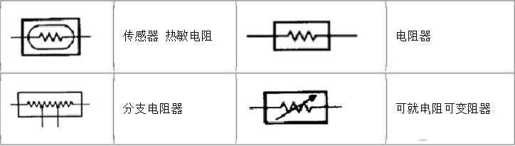
Thermistor symbol
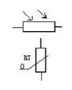
What does the letter in the electrical symbol of the thermistor mean? Some are o, some are vm, and the one with O is a thermistor. With U is the varistor thermistor symbol thermistor resistance value varies with the outside temperature. Some are negative temperature coefficients, expressed by NTC; some are positive temperature coefficients, expressed by PTC. The temperature is expressed by θ or t°. Its text symbol is "RT". In the circuit diagram, the signs of the photoresistor and the thermistor are expressed as:
8, no action current INk: The current flowing through the PTC thermistor is insufficient to cause the PTC thermistor to rise above the Curie temperature, which is called a non-operating current. The maximum value of the non-operating current is called the maximum non-operating current.
The main features of the thermistor are:
1. High sensitivity. The temperature coefficient of resistance is 10 to 100 times larger than that of metal, and the temperature change of 10-6 ° C can be detected;
2. Wide operating temperature range. Normal temperature devices are suitable for -55 ° C ~ 315 ° C, high temperature devices are suitable for temperatures above 315 ° C (currently up to 2000 ° C), low temperature devices are suitable for -273 ° C ~ 55 ° C;
3. Small size. Ability to measure the temperature of voids, cavities and blood vessels in the body that cannot be measured by other thermometers;
4, easy to use, the resistance value can be arbitrarily selected between 0.1 ~ 100kΩ;
5, easy to process into complex shapes, can be produced in large quantities;
6. Good stability and strong overload capability.
Thermistor symbol
What does the letter in the electrical symbol of the thermistor mean? Some are o, some are vm, and the one with O is a thermistor. With U is the varistor thermistor symbol thermistor resistance value varies with the outside temperature. Some are negative temperature coefficients, expressed by NTC; some are positive temperature coefficients, expressed by PTC. The temperature is expressed by θ or t°. Its text symbol is "RT". In the circuit diagram, the signs of the photoresistor and the thermistor are expressed as:
Representation symbol of the thermistor in the circuit diagram


