Polymer resettable fuse Selection and Application
What is polymer resettable fuse?
Polymer positive temperature coefficient fuses can help protect against over-current surges and over-temperature faults. Polymer PTC can limit the flow of dangerous large currents under fault conditions. But it is different from traditional fuses that must be replaced only once. The PTC fuse carefully built by YAXUN for twelve years can be reset after troubleshooting and disconnecting the power supply. Reduce product costs, service and maintenance costs.
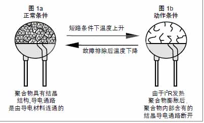
PTC fuses are made of polymer PTC materials mixed with nano conductor particles. As shown in Figure 1, the raw material tightly binds the conductor to the crystalline structure at normal temperature, forming a low-impedance link. However, when a large current passes through or the ambient temperature rises, causing the device temperature to be higher than the operating temperature, the conductors in the polymer melt and become irregularly arranged, the volume expands and leads to a rapid increase in impedance.
In the normal working state, the resistance of this PPTC device is much smaller than the rest of the resistance in the circuit. But in response to an overcurrent situation, the resistance of the PPTC is increased (action), thereby reducing the current in the circuit to a value that can be safely carried by any component. This protection action is caused by the heat generated by the internal I2RT or the high temperature of the surrounding devices of the PTC fuse, which causes the PPTC temperature to rise rapidly.
The operating principle of PTC fuses
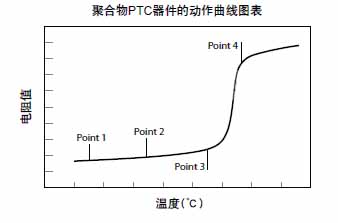
The operating principle of PPTC fuse is a kind of energy balance. As shown in Figure 3, when current flows through the PPTC fuse, heat will be generated due to the relationship of I2RT, and all or part of the generated heat will be dissipated to the environment. Anything that is not emitted will increase the temperature of the PPTC fuse.
At Point 1 in Figure 3, the temperature is low, and the heat generated and the heat dissipated reach a balance. However, when more current flows or the ambient temperature is higher, higher heat will be generated, which will increase the temperature of the PTC fuse. However, when the increase in current or ambient temperature is not significant, the heat generated by the PPTC fuse can be dissipated to the environment and balance at Point 2.
When the current or ambient temperature increases again, the PPTC fuse will reach a higher temperature as shown in Point 3. If the current or ambient temperature continues to increase at this time, the heat energy generated will be greater than that emitted, causing the temperature of the PPTC fuse to increase rapidly. At this stage, a small temperature change will cause a substantial increase in resistance. This phenomenon can be seen by Point 3 and Point 4 on the figure. At this time, the PPTC fuse is in the protective state of action, and the increase in impedance limits the passage of current and protects the equipment from damage. As mentioned above, when the ambient temperature rises, the resistance of the PTC thermistor will also increase, so as to reach the high impedance state of Point 4 without the need for external current. When the temperature drops, the PPTC fuse returns to a low impedance state with the characteristics of a thermistor. This phenomenon can be used as temperature sensing control.
Example of holding and operating current as a function of temperature
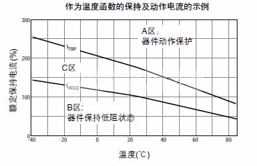
Figure 4 illustrates the holding and operating current characteristics of a PPTC fuse as a function of temperature. One such curve can be defined for each available device. Area A illustrates the combination of current and temperature when the PPTC fuse will operate (turn to a high resistance state) to protect the circuit. Area B illustrates the combination of current and temperature that the PPTC fuse will allow the circuit to work properly. In zone C, the device may operate or remain in a low resistance state (depending on the resistance of a single device).
PTC fuse selection method and steps
Step 1: Determine the circuit parameters
You need to determine the following parameters of the circuit:
Maximum working environment temperature
Standard working current
Maximum working voltage
Maximum interrupt current
Step 2: Choose a PTC fuse that can accommodate the maximum ambient temperature and standard operating current of the circuit
Use the reduction ratio table [Ambient temperature (℃) holding current (A)] and select the temperature that best matches the maximum ambient temperature of the circuit. Browse this column to see a value equal to or greater than the standard operating current of the circuit. Now look at the far left of the row to see the series of PPTC fuses most suitable for the circuit.
Step 3: Compare the maximum electrical rating of the PPTC fuse with the maximum operating voltage and interrupt current of the circuit
Use the electrical characteristics table to verify that the parts you selected in step 2 will use the circuit’s maximum operating voltage and interrupt current. Check the maximum operating voltage (Vmax) and maximum interrupt current (Imax) of the device. Ensure that Vmax and Imax are greater than or equal to the maximum operating voltage and maximum interrupting current of the circuit.
Step 4: Determine the operating time of the PPTC fuse
The protection action time is the amount of time it takes to switch the device to a high resistance state when the fault current passes through the PTC. In order to provide the expected protection function, it is important to clarify the operating time of the PTC fuse. If the device you select moves too fast, abnormal or malfunctioning may occur. If the PTC protection action is too slow, the protected device may be damaged before the device operates and limits the current.
Use the protection action time curve at 25°C to determine whether the action time characteristics of the PTC fuse are acceptable under the expected fault current. If not, go back to step 2 to select another alternative PTC device.
Step 5: Verify the ambient operating temperature
Ensure that the minimum and maximum ambient temperature of the application is within the working temperature range of PTC insurance. The operating temperature range of most PTC insurance is between -40°C to 85°C, and can reach 125°C in some special cases.
Step 6: Verify the dimensions of the PTC fuse
Use the size chart to compare the size of your selected PTC fuse with the space conditions of the application.
Parameter definition description:
IH Maximum working current at 25℃ ambient temperature
The minimum current of PTC fuse protection under IT 25℃ ambient temperature
The maximum working voltage of Vmax PTC fuse safely disconnected, also known as Maximum Device Voltage, Maximum Voltage, Vmax,
Max Interrupt Voltage
Imax The maximum fault current at which the PTC fuse can operate safely at an ambient temperature of 25℃
Rmax The initial maximum resistance of the PTC fuse before it operates at an ambient temperature of 25°C
Rmin The initial minimum resistance value of the PTC fuse before it operates at an ambient temperature of 25°C
Polymer positive temperature coefficient fuses can help protect against over-current surges and over-temperature faults. Polymer PTC can limit the flow of dangerous large currents under fault conditions. But it is different from traditional fuses that must be replaced only once. The PTC fuse carefully built by YAXUN for twelve years can be reset after troubleshooting and disconnecting the power supply. Reduce product costs, service and maintenance costs.
PTC fuses are made of polymer PTC materials mixed with nano conductor particles. As shown in Figure 1, the raw material tightly binds the conductor to the crystalline structure at normal temperature, forming a low-impedance link. However, when a large current passes through or the ambient temperature rises, causing the device temperature to be higher than the operating temperature, the conductors in the polymer melt and become irregularly arranged, the volume expands and leads to a rapid increase in impedance.
Polymer fuse is used as overcurrent protection
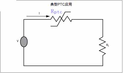
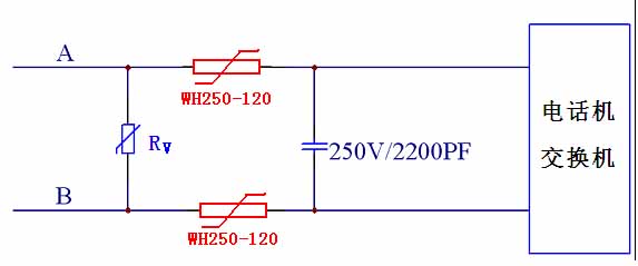
In the circuit, the positive temperature coefficient overcurrent protection device is used in series in the circuit. When the current increases rapidly, the PPTC fuse changes from low resistance to high resistance to protect the circuit. This is called PPTC fuse ‘action’, as shown in Figure 2 is a typical application.
Self-recovery fuse application (PTC application)
In the normal working state, the resistance of this PPTC device is much smaller than the rest of the resistance in the circuit. But in response to an overcurrent situation, the resistance of the PPTC is increased (action), thereby reducing the current in the circuit to a value that can be safely carried by any component. This protection action is caused by the heat generated by the internal I2RT or the high temperature of the surrounding devices of the PTC fuse, which causes the PPTC temperature to rise rapidly.
The operating principle of PTC fuses
The operating principle of PPTC fuse is a kind of energy balance. As shown in Figure 3, when current flows through the PPTC fuse, heat will be generated due to the relationship of I2RT, and all or part of the generated heat will be dissipated to the environment. Anything that is not emitted will increase the temperature of the PPTC fuse.
At Point 1 in Figure 3, the temperature is low, and the heat generated and the heat dissipated reach a balance. However, when more current flows or the ambient temperature is higher, higher heat will be generated, which will increase the temperature of the PTC fuse. However, when the increase in current or ambient temperature is not significant, the heat generated by the PPTC fuse can be dissipated to the environment and balance at Point 2.
When the current or ambient temperature increases again, the PPTC fuse will reach a higher temperature as shown in Point 3. If the current or ambient temperature continues to increase at this time, the heat energy generated will be greater than that emitted, causing the temperature of the PPTC fuse to increase rapidly. At this stage, a small temperature change will cause a substantial increase in resistance. This phenomenon can be seen by Point 3 and Point 4 on the figure. At this time, the PPTC fuse is in the protective state of action, and the increase in impedance limits the passage of current and protects the equipment from damage. As mentioned above, when the ambient temperature rises, the resistance of the PTC thermistor will also increase, so as to reach the high impedance state of Point 4 without the need for external current. When the temperature drops, the PPTC fuse returns to a low impedance state with the characteristics of a thermistor. This phenomenon can be used as temperature sensing control.
Example of holding and operating current as a function of temperature
Figure 4 illustrates the holding and operating current characteristics of a PPTC fuse as a function of temperature. One such curve can be defined for each available device. Area A illustrates the combination of current and temperature when the PPTC fuse will operate (turn to a high resistance state) to protect the circuit. Area B illustrates the combination of current and temperature that the PPTC fuse will allow the circuit to work properly. In zone C, the device may operate or remain in a low resistance state (depending on the resistance of a single device).
The operating principle of polymer PPTC fuse
Figure 5 shows a pair of typical operating curve pairs of polymerized PTC fuses in still air at 0°C and 75°C. These curves are different because the heat required to actuate the device comes from the electrical I2RT heating and the device environment. The heat input of the environment at 75°C is much larger than that at 0°C, so the additional I2RT required for the action is relatively small, resulting in a lower operating current within a given operating time. (Or faster protection under a given operating current)PPTC resistance recovery characteristics after protection action
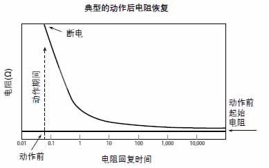
Figure 6 shows the typical behavior of a PTC fuse that operates and subsequently cools down. In this figure, we can clearly see that even after several hours, the resistance of the PTC is still greater than the initial resistance. The process of decreasing the resistance value will continue for a longer period of time, and the final resistance will approach the initial resistance value. According to the experiment, it can be used again within 30 seconds after the power is cut off. (If it is inside the motor, it can be used after the motor has cooled down.).PTC fuse selection method and steps
Step 1: Determine the circuit parameters
You need to determine the following parameters of the circuit:
Maximum working environment temperature
Standard working current
Maximum working voltage
Maximum interrupt current
Step 2: Choose a PTC fuse that can accommodate the maximum ambient temperature and standard operating current of the circuit
Use the reduction ratio table [Ambient temperature (℃) holding current (A)] and select the temperature that best matches the maximum ambient temperature of the circuit. Browse this column to see a value equal to or greater than the standard operating current of the circuit. Now look at the far left of the row to see the series of PPTC fuses most suitable for the circuit.
Step 3: Compare the maximum electrical rating of the PPTC fuse with the maximum operating voltage and interrupt current of the circuit
Use the electrical characteristics table to verify that the parts you selected in step 2 will use the circuit’s maximum operating voltage and interrupt current. Check the maximum operating voltage (Vmax) and maximum interrupt current (Imax) of the device. Ensure that Vmax and Imax are greater than or equal to the maximum operating voltage and maximum interrupting current of the circuit.
Step 4: Determine the operating time of the PPTC fuse
The protection action time is the amount of time it takes to switch the device to a high resistance state when the fault current passes through the PTC. In order to provide the expected protection function, it is important to clarify the operating time of the PTC fuse. If the device you select moves too fast, abnormal or malfunctioning may occur. If the PTC protection action is too slow, the protected device may be damaged before the device operates and limits the current.
Use the protection action time curve at 25°C to determine whether the action time characteristics of the PTC fuse are acceptable under the expected fault current. If not, go back to step 2 to select another alternative PTC device.
Step 5: Verify the ambient operating temperature
Ensure that the minimum and maximum ambient temperature of the application is within the working temperature range of PTC insurance. The operating temperature range of most PTC insurance is between -40°C to 85°C, and can reach 125°C in some special cases.
Step 6: Verify the dimensions of the PTC fuse
Use the size chart to compare the size of your selected PTC fuse with the space conditions of the application.
Parameter definition description:
IH Maximum working current at 25℃ ambient temperature
The minimum current of PTC fuse protection under IT 25℃ ambient temperature
The maximum working voltage of Vmax PTC fuse safely disconnected, also known as Maximum Device Voltage, Maximum Voltage, Vmax,
Max Interrupt Voltage
Imax The maximum fault current at which the PTC fuse can operate safely at an ambient temperature of 25℃
Rmax The initial maximum resistance of the PTC fuse before it operates at an ambient temperature of 25°C
Rmin The initial minimum resistance value of the PTC fuse before it operates at an ambient temperature of 25°C


