PT100 thermal resistance temperature measurement circuit design details - circuit diagram design
This paper analyzes the working principle and design basis of the functional circuit such as constant current source signal conditioning analog-to-digital conversion in the temperature measurement system, and gives the circuit parameters. Temperature is one of the four parameters of the chemical production process. The temperature sensor Pt100 is widely used for temperature measurement below 650 °C due to its small size, high accuracy and good stability.
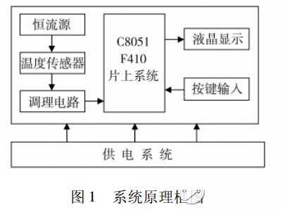
The Pt100 temperature measurement system uses the C8051F410 system-on-chip as the control core. The principle block diagram of the system is shown in Figure 1. Including C8051F410 on-chip system constant current source drive circuit signal acquisition circuit signal conditioning circuit display circuit button circuit and power supply circuit 7 components.
System block diagram
Constant current source circuit
The constant current source driving circuit is responsible for driving the temperature sensor Pt100, and converting its sensed temperature-varying resistance signal into a measurable voltage signal to realize R-V conversion. The constant current source circuit is composed of the op amp OP07 reference voltage source resistor and the triode. To avoid the influence of the heat generated by the excitation current, the constant current source is designed to be 1 mA. The specific implementation is shown in Figure 3. VZ1 is a 2.5V voltage regulator, ie U1-U3=2.5V; According to the principle of the short circuit of the op amp, the voltage of the non-inverting terminal and the voltage of the inverting terminal of the operational amplifier OP07 are equal, that is, U2=U3; Therefore, the voltage U1-U2 across the resistor R31 = 2.5V; the current flowing through R31 can be calculated as 2. 5V/2. 5K =1mA. According to the principle of the operational amplifier virtual disconnection, it can be seen that the current flowing through R31 will flow almost all into the composite pipe without flowing into the opposite end of the operational amplifier. The output current of the collector of the composite tube is 1 mA, which realizes the design of a high-precision constant current source.
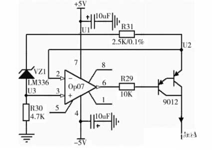
Figure 3 constant current source circuit
Key points in the design:
A precision 2.5V voltage reference is provided by the LM336; R31 is a precision wire wound resistor with good stability; The composite tube made up of two pieces of 9012 increases the current amplification factor value, reduces the temperature drift coefficient, and stabilizes the constant current value.
Edit Comment:
This paper briefly introduces the design of the RTD temperature measurement circuit. The hardware of the temperature measurement system uses a three-wire connection method to eliminate the influence of the wire resistance on the measurement results. The system interference signal is suppressed by the hardware filter circuit and the software digital filtering processing method, which greatly improves the accuracy and stability of the measurement system.
The Pt100 temperature measurement system uses the C8051F410 system-on-chip as the control core. The principle block diagram of the system is shown in Figure 1. Including C8051F410 on-chip system constant current source drive circuit signal acquisition circuit signal conditioning circuit display circuit button circuit and power supply circuit 7 components.
System block diagram
The constant current source drives the temperature sensor Pt100 to convert the resistance signal (80.31 to 280.98) into a weak voltage signal (0.08 to 0.28V). In the signal conditioning circuit is converted to 0 ~ 2. The voltage signal between 2V, the C8051F410 on-chip system A/D samples the voltage signal. According to the Pt100 index table and the relationship between the sampling voltage and the resistance, the accurate measured temperature value is finally obtained by software processing, and the corresponding digital quantity is sent to the display circuit for display.
Hardware circuit design
C8051F410 system-on-chip basic peripheral interface
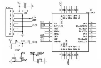
The C8051F410 system on chip is the control core of this temperature measurement system. Its basic peripheral interface circuit is an auxiliary circuit that ensures the normal operation of the system. It includes basic peripheral circuits such as JATG interface power supply decoupling reference filter power-on reset required for C8051F410 system-on-chip operation. as shown in picture 2.
Hardware circuit design
C8051F410 system-on-chip basic peripheral interface
The C8051F410 system on chip is the control core of this temperature measurement system. Its basic peripheral interface circuit is an auxiliary circuit that ensures the normal operation of the system. It includes basic peripheral circuits such as JATG interface power supply decoupling reference filter power-on reset required for C8051F410 system-on-chip operation. as shown in picture 2.
figure 2 C8051F410 basic peripheral circuit
Constant current source circuit
The constant current source driving circuit is responsible for driving the temperature sensor Pt100, and converting its sensed temperature-varying resistance signal into a measurable voltage signal to realize R-V conversion. The constant current source circuit is composed of the op amp OP07 reference voltage source resistor and the triode. To avoid the influence of the heat generated by the excitation current, the constant current source is designed to be 1 mA. The specific implementation is shown in Figure 3. VZ1 is a 2.5V voltage regulator, ie U1-U3=2.5V; According to the principle of the short circuit of the op amp, the voltage of the non-inverting terminal and the voltage of the inverting terminal of the operational amplifier OP07 are equal, that is, U2=U3; Therefore, the voltage U1-U2 across the resistor R31 = 2.5V; the current flowing through R31 can be calculated as 2. 5V/2. 5K =1mA. According to the principle of the operational amplifier virtual disconnection, it can be seen that the current flowing through R31 will flow almost all into the composite pipe without flowing into the opposite end of the operational amplifier. The output current of the collector of the composite tube is 1 mA, which realizes the design of a high-precision constant current source.
Figure 3 constant current source circuit
Key points in the design:
A precision 2.5V voltage reference is provided by the LM336; R31 is a precision wire wound resistor with good stability; The composite tube made up of two pieces of 9012 increases the current amplification factor value, reduces the temperature drift coefficient, and stabilizes the constant current value.
Edit Comment:
This paper briefly introduces the design of the RTD temperature measurement circuit. The hardware of the temperature measurement system uses a three-wire connection method to eliminate the influence of the wire resistance on the measurement results. The system interference signal is suppressed by the hardware filter circuit and the software digital filtering processing method, which greatly improves the accuracy and stability of the measurement system.


