Overcurrent protection circuit design scheme with different current detection methods
Current Detection Using Current Sensor
The working principle of the overcurrent detection sensor is shown in Figure 1. The converter secondary current obtained by the converter is converted to a voltage by I/V. After the voltage is DC, the voltage comparator compares with the set value, and if the DC voltage is greater than the set value, a discrimination signal is issued. However, such a detection sensor is generally used to monitor the load current of the inductive power supply, and the following measures are required for this purpose. Since the inductive power supply is activated, the starting current is several times the rated value, which is much larger than the current at the end of the start-up. Therefore, in the case of simply monitoring the current battery, the inductive power supply should obtain the necessary output signal when starting, and the timer must be used to set the prohibition time. The unnecessary signal is not output before the start of the induction power supply, and after the timing is over, it is transferred to the predetermined monitoring state.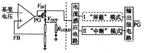
Start surge current limiting circuit
When the switching power supply is powered up, it will generate a high surge current. Therefore, a soft start device that prevents surge current must be installed at the input of the power supply to effectively reduce the inrush current to the allowable range. The inrush current is mainly caused by the charging of the filter capacitor. At the moment when the switch tube starts to conduct, the capacitor exhibits a lower impedance to the AC. If no protective measures are taken, the inrush current can approach hundreds of A.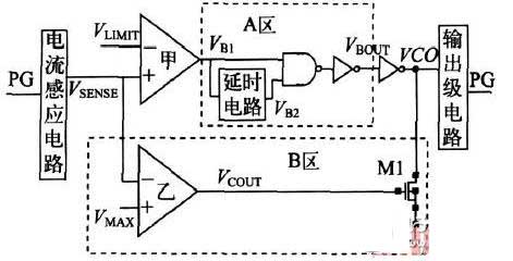
The input of the switching power supply generally uses a capacitor rectifier filter circuit as shown in Figure 2. The filter capacitor C can be selected from low frequency or high frequency capacitors. If a low frequency capacitor is used, it is necessary to connect the high frequency capacitor of the same capacity to bear the charge and discharge current. The current limiting resistor Rsc that is connected between rectification and filtering in the figure is to prevent the impact of the inrush current. Rsc limits the charging current of capacitor C when it is turned on. After a period of time, when the voltage on C reaches the preset value or the voltage on the capacitor C1 reaches the operating voltage of the relay T, the Rsc is short-circuited and completed. At the same time, circuits such as thyristors can be used to short the Rsc. When the switch is closed, the capacitor C is charged through the Rsc because the thyristor is turned off. After a period of time, the thyristor is turned on, thereby shorting the current limiting resistor Rsc.
Current limiting circuit using base drive circuit
In general, the base control circuit is used to isolate the control circuit of the power supply from the switching transistor. The control circuit and the output circuit are common, and the current limiting circuit can be directly connected to the output circuit. The working principle is shown in FIG. When the output is overloaded or shorted, V1 is turned on, and the voltage across R3 increases and is compared with the reference voltage at the inverting terminal of the comparator. Control the PWM signal on and off.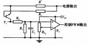
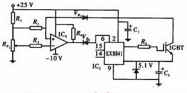
By detecting the Vce of the IGBT
When the power output is overloaded or short-circuited, the Vce value of the IGBT becomes larger. According to this principle, the circuit can be protected. For this purpose, the dedicated driver EXB841 is usually used, and its internal circuit can well complete the down-gate and soft-off, and has an internal delay function to eliminate the malfunction caused by interference. The working principle is shown in Figure 4. The Vce containing the IGBT overcurrent information is not sent directly to the collector voltage monitoring pin 6 of the EXB841, but via the fast recovery diode VD1. The output of the comparator IC1 is connected to the pin 6 of the EXB841, thereby eliminating the case where the forward voltage drop varies with the current, and the threshold comparator is used to improve the accuracy of the current detection. If an overcurrent occurs, the driver: EXB841's low-speed shutdown circuit will slowly turn off the IGBT, thus avoiding the collector current spike to damage the IGBT device.