How to use NTC thermistor to limit surge current?
At the moment when the power circuit is energized, the energy of the external power source is first transferred to the input filter capacitor. This instant generates a large surge current, if not limited, it is easy to damage the fuse and subsequent rectifier diodes and other peripheral electronic components. Therefore, in the circuit design, you need to consider how to limit the inrush current. In this article, we will first introduce how to use NTC thermistor to limit the inrush current, then how to choose the NTC thermistor, and finally how to use the relay to further reduce the power consumption on the NTC thermistor.
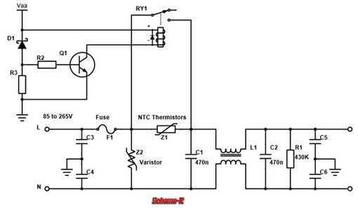
Figure 1 below shows the front end of a typical AC-DC power supply circuit. In the figure, Z1 is an NTC thermistor. This resistor acts as an instantaneous current limit protection when the power supply is energized.
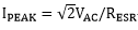
The moment when the power circuit is energized, it can be seen as the process of charging the filter capacitor (C1, C2 in Figure 1 below). The magnitude of the surge current can be estimated by dividing the voltage by the equivalent series resistance of the filter capacitor.
For example, if you use a 10Ω NTC thermistor at 25°C, assuming that the equivalent series resistance of the filter capacitor is 1Ω, the inrush current will be reduced to about one-tenth. It can be seen that the greater the resistance of the NTC thermistor, the better the effect of limiting the inrush current.
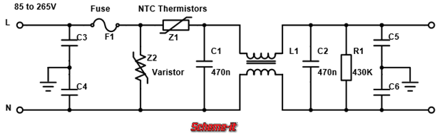
Figure 1, AC-DC power circuit front end

How to choose NTC thermistor?
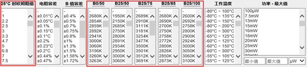
The YAXUN website lists a number of NTC thermistor parameters, where the "ohmic value of 25 °C" and the B value are two important parameters. The "ohmic value of 25 °C" determines the current limiting capability of the NTC thermistor at the moment the power supply circuit is energized. According to the B value, the resistance value of the NTC thermistor to the final temperature can be calculated.
YAXUN NTC Thermistor
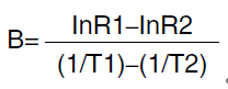
So how do you choose and calculate B? The B value range (K) is the thermal index of the negative temperature coefficient thermistor, reflecting the change in resistance between the two temperatures.
It is defined as the ratio of the difference between the natural logarithm of the zero power resistance value at two temperatures and the difference between the reciprocal of this temperature.
From the above equation, R1 and R2 are resistance values (Ω) at absolute temperatures T1 and T2, respectively. Among them, B0/50, B25/50, B25/75, B25/85, and B25/100 correspond to B values between different temperatures.
If we want the resistance to be 10Ω at 25°C, the resistance is 2Ω when the temperature is 85°C, and the equation above can be obtained. The B value needs 2864K or more.
Finally, the comprehensive screening, quickly found EPCOS (TDK) B57234S0100M000 B value of 3060K, 25 °C 10, power 3.2W, basically meet the requirements.
What should I do to further reduce the loss on the NTC?
For some applications, reducing power consumption is especially critical, and the power loss on NTC thermistors is not negligible.
A relay can be connected in parallel with the NTC thermistor to reduce the power consumption of the NTC thermistor. As shown below, Vaa is a digital/analog power supply for subsequent circuits that are AC-DC converted, such as 5V/12V.
The relay is initially disconnected. When Vaa gradually reaches its own voltage, the Zener diode D1 is turned on, the transistor Q1 is turned on, and the relay RY1 is closed, which is equivalent to short-circuiting the current limiting NTC thermistor Z1.
Of course, a normal resistor can also be used here instead of the NTC thermistor to act as a current limiting resistor. In the case of ordinary resistors used in conjunction with relays, the resistance is more stable without temperature and the effect of current limiting is more stable.
For some low cost, lower power supply circuits, it is often common to use NTC thermistors to limit inrush current. For medium/high power supply circuits and applications where power conversion efficiency is critical, relays can be used to further reduce power dissipation on NTC thermistors.
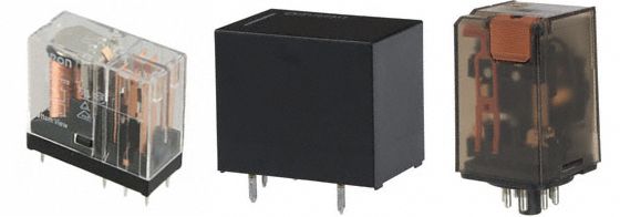
YAXUN power relay
YAXUN more different relay options
to sum up
At the moment when the power circuit is energized, the energy of the external power source is first transferred to the input filter capacitor. The NTC thermistor can be used to limit the inrush current while reducing the resistance when the temperature rises, thus reducing the power consumption of the NTC thermistor itself.
Finally, peripheral circuits such as relays can be used to further reduce the power dissipation of the NTC thermistor as a current limiting resistor.
Limiting inrush current, why use NTC?
NTC (negative temperature coefficient) A thermistor is a thermistor that has a negative temperature coefficient with a decreasing exponential relationship with increasing temperature.Figure 1 below shows the front end of a typical AC-DC power supply circuit. In the figure, Z1 is an NTC thermistor. This resistor acts as an instantaneous current limit protection when the power supply is energized.
The moment when the power circuit is energized, it can be seen as the process of charging the filter capacitor (C1, C2 in Figure 1 below). The magnitude of the surge current can be estimated by dividing the voltage by the equivalent series resistance of the filter capacitor.
The larger the current value, the greater the destructive power to the surrounding circuits.
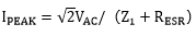
In order to solve this problem, the easiest way is to add an NTC thermistor (Z1 in Figure 1 below) to reduce the magnitude of the surge current. The surge resistance at the moment of power-on is equivalent to the voltage divided by the sum of the equivalent series resistance of the NTC thermistor and the filter capacitor.
In order to solve this problem, the easiest way is to add an NTC thermistor (Z1 in Figure 1 below) to reduce the magnitude of the surge current. The surge resistance at the moment of power-on is equivalent to the voltage divided by the sum of the equivalent series resistance of the NTC thermistor and the filter capacitor.
For example, if you use a 10Ω NTC thermistor at 25°C, assuming that the equivalent series resistance of the filter capacitor is 1Ω, the inrush current will be reduced to about one-tenth. It can be seen that the greater the resistance of the NTC thermistor, the better the effect of limiting the inrush current.
Figure 1, AC-DC power circuit front end
Of course, the resistance value of NTC thermistor is not the bigger the better. The larger the resistance, the greater the power consumed. The negative temperature coefficient NTC thermistor balances well with limiting inrush current and power consumption.
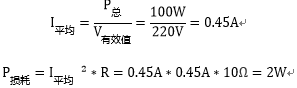
For a 100W power supply circuit, assume a 10Ω NTC thermistor at 25°C. The NTC thermistor will have a power loss of about 2W when the power is turned on and the ambient temperature is 25 °C:
For a 100W power supply circuit, assume a 10Ω NTC thermistor at 25°C. The NTC thermistor will have a power loss of about 2W when the power is turned on and the ambient temperature is 25 °C:
Then as the current flows through the NTC thermistor, the temperature gradually rises. Assuming that the NTC thermistor is heated to 85 ° C, the resistance drops to about 2 Ω, and the loss on the NTC thermistor will drop to about 0.4 W. As shown below
How to choose NTC thermistor?
The YAXUN website lists a number of NTC thermistor parameters, where the "ohmic value of 25 °C" and the B value are two important parameters. The "ohmic value of 25 °C" determines the current limiting capability of the NTC thermistor at the moment the power supply circuit is energized. According to the B value, the resistance value of the NTC thermistor to the final temperature can be calculated.
YAXUN NTC Thermistor
Figure 2, comparison and screening of NTC parameters on YAXUN website
So how do you choose and calculate B? The B value range (K) is the thermal index of the negative temperature coefficient thermistor, reflecting the change in resistance between the two temperatures.
It is defined as the ratio of the difference between the natural logarithm of the zero power resistance value at two temperatures and the difference between the reciprocal of this temperature.
From the above equation, R1 and R2 are resistance values (Ω) at absolute temperatures T1 and T2, respectively. Among them, B0/50, B25/50, B25/75, B25/85, and B25/100 correspond to B values between different temperatures.
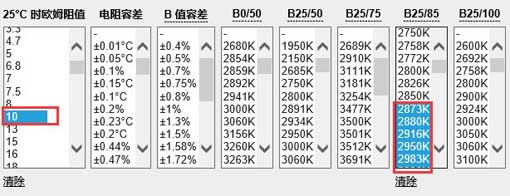
If we want the resistance to be 10Ω at 25°C, the resistance is 2Ω when the temperature is 85°C, and the equation above can be obtained. The B value needs 2864K or more.
Figure 3. Screening for appropriate NTC thermistor parameters from the YAXUN website
Finally, the comprehensive screening, quickly found EPCOS (TDK) B57234S0100M000 B value of 3060K, 25 °C 10, power 3.2W, basically meet the requirements.
What should I do to further reduce the loss on the NTC?
For some applications, reducing power consumption is especially critical, and the power loss on NTC thermistors is not negligible.
A relay can be connected in parallel with the NTC thermistor to reduce the power consumption of the NTC thermistor. As shown below, Vaa is a digital/analog power supply for subsequent circuits that are AC-DC converted, such as 5V/12V.
The relay is initially disconnected. When Vaa gradually reaches its own voltage, the Zener diode D1 is turned on, the transistor Q1 is turned on, and the relay RY1 is closed, which is equivalent to short-circuiting the current limiting NTC thermistor Z1.
Of course, a normal resistor can also be used here instead of the NTC thermistor to act as a current limiting resistor. In the case of ordinary resistors used in conjunction with relays, the resistance is more stable without temperature and the effect of current limiting is more stable.
Figure 4. Using a relay to reduce the power consumption of the NTC thermistor
For some low cost, lower power supply circuits, it is often common to use NTC thermistors to limit inrush current. For medium/high power supply circuits and applications where power conversion efficiency is critical, relays can be used to further reduce power dissipation on NTC thermistors.
YAXUN power relay
YAXUN more different relay options
to sum up
At the moment when the power circuit is energized, the energy of the external power source is first transferred to the input filter capacitor. The NTC thermistor can be used to limit the inrush current while reducing the resistance when the temperature rises, thus reducing the power consumption of the NTC thermistor itself.
Finally, peripheral circuits such as relays can be used to further reduce the power dissipation of the NTC thermistor as a current limiting resistor.


