Design of a High Precision Temperature Measurement System Based on PT1000
Precision chemistry, biomedicine, fine chemicals, precision instruments and other fields have extremely high requirements for temperature control accuracy, and the core of temperature control is temperature measurement. Measuring temperature with platinum resistance is an effective high-precision temperature measurement method, but it has the following difficulties: Lead resistance, self-heating effect, component drift, and platinum resistance sensor accuracy. Among them, reducing the influence of lead resistance is a key point for high-precision measurement. For the self-heating effect, according to the component heating formula P=I2R, the current flowing through the component must be made small enough to make the heat generation small, and the sensor can detect the correct temperature. However, too small a current will reduce the signal-to-noise ratio, and the accuracy is difficult to guarantee. In addition, some components and instruments are difficult to meet component drift and platinum resistance sensor accuracy requirements.
Our company has proposed a high-precision temperature measurement scheme using platinum resistance as the temperature measuring component, which solves some demanding problems of high-precision measurement on the hardware circuit, but the accuracy is not good (±0.4 °C); The precision temperature measurement system designed with MAX1402, AT89C51 and Pt500 platinum resistors solves the basic high-precision problem, but the system consumes a lot of power and the accuracy is still poor. The high-precision measurement scheme with the negative temperature coefficient thermistor as the core solves the problem of high precision. However, the cost performance is not high, the implementation effect is not good, the temperature resolution can reach 0.01 ° C, and the temperature measurement accuracy only reaches O. 1 ° C. Here, a three-wire constant current source driving scheme is proposed to overcome the lead resistance and self-heating effect, and the component drift and platinum resistance sensor accuracy calibration are realized by using the single-chip system correction control scheme. Finally, the MLS numerical algorithm is used in the host computer to achieve noise cancellation, which greatly improves the temperature measurement accuracy and stability.
1. High precision measurement scheme and principle
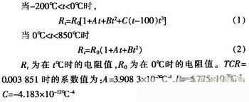
The platinum resistance sensor is a temperature sensor made by utilizing the physical properties of the metal platinum (Pt) resistance value as a function of temperature. The key to temperature measurement with platinum resistance as the temperature measuring element is to accurately measure the resistance value of the platinum resistance sensor. According to the IEC751 international standard, the commonly used PT1000 (Ro=1 000 Ω) is a platinum resistor uniformly designed with the temperature coefficient TCR=0.003 851 as the standard. Its temperature resistance characteristics are:
2. System circuit design
2.1 Three-wire constant current source drive circuit
The constant current source driving circuit is responsible for driving the temperature sensor Pt1000 to convert its sensed temperature-varying resistance signal into a measurable voltage signal. In this system, the constant current source required has a constant output current, good temperature stability, and large output resistance. The output current is less than 0.5 mA (the upper limit of Pt1000 has no self-heating effect), the load is grounded at one end, and the polarity of the output current can be changed.
Since the influence of temperature on the integrated operational amplifier parameters is not as significant as that of the transistor or FET parameters, the constant current source composed of the integrated operational amplifier has the advantages of better stability and higher constant current performance. Especially in the case where the load end needs to be grounded, it has been widely used. Therefore, the dual op amp constant current source shown in Figure 2 is used. The amplifier UA1 constitutes an adder, UA2 constitutes a follower, and UA1 and UA2 select a low noise, low offset, high open loop gain bipolar operational amplifier OP07.
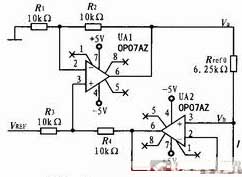
Let the potentials at the upper and lower ends of the reference resistor Rref in Fig. 2 respectively Va and Vb, Va is the output of the in-phase adder UA1. When the resistor R1=R2 and R3=R4, then Va=VREFx+Vb, so the output current of the constant current source is:

It can be seen that the dual op amp constant current source has the following remarkable features:
1) The load can be grounded;
2) When the op amp is powered by dual power supplies, the output current is bipolar;
3) The constant current magnitude is achieved by changing the input reference reference VREF or adjusting the reference resistor Rref0. It is easy to obtain stable small current and compensated calibration.
Due to the mismatch of the resistor, the voltage across the reference resistor Rref0 will be affected by the terminal voltage Vb of its driving load. At the same time, because it is a constant current source, Vb will definitely change with the load, which will affect the stability of the constant current source. Obviously this is unacceptable for high precision constant current sources. Therefore, the selection principle of the four resistors R1, R2, R3, and R4 is that the mismatch should be as small as possible, and the mismatch size of each pair of resistors should be the same. In practice, a large number of precision resistors of the same batch can be screened, and four resistors with similar resistance values are selected.
2.2 Signal Conditioning Circuit
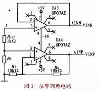
The signal conditioning circuit is shown in Figure 3. The amplifier UA3 unit-amplifies the terminal voltage of the reference resistor Rref to obtain a differential amplifier inverting input signal. Its value is:
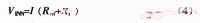
The amplifier UA4 amplifies the terminal voltage of the temperature sensor Rt (PT1000) by 2 times to obtain the forward input signal of the differential amplifier. Its value is:

2.3 A / D conversion circuit
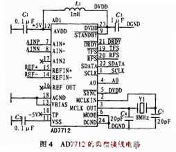
The A/D conversion circuit is implemented by an integrated A/D converter AD7712, which will also perform differential amplification of the instrumentation amplifier using its internal PGA. The AD7712 is a high precision A/D converter suitable for low frequency measurements. The chip contains two input channels, AIN1 and AIN2, which convert the analog signal into a serial data output. The principle circuit of data conversion acquisition using AD7712 is shown in Figure 4. It needs to be configured during actual work. The differential input channel AIN1 is selected and the input signal polarity is bipolar.
The error of the measurement result mainly comes from the error of the reference resistors Rref and Rref0, and the error of the differential amplification factor k and the conversion output of the A/D converter. In order to achieve the required measurement accuracy, the reference resistors Rref, Rref0 will use a custom UPR plastic foil foil resistor, which has an O. 05% initial accuracy, less than 5 ppm temperature stability. The nonlinear error of AD7712 is less than O. 001 5%, gain temperature stability is less than 2 ppm. And the AD7712 can be calibrated by a single-chip microcomputer to reduce its nonlinear error and gain error.
3 Calibration and measurement results
3.1 Measurement system calibration
The measurement system was first calibrated using a high-precision resistor box (error 5 ppm) instead of the Pt1000. According to the measured Pt1000 resistance/temperature relationship calibration data shown in Equation 2, the corresponding test temperature point nominal value is set by changing the value of the resistance box. After measuring system, A/D sampling and PC program calculation, the measured temperature display value is obtained. According to the initial measurement data, the measurement circuit and the compensation voltage are calibrated, and the calibration data of the measurement system is obtained as shown in Table 1.
Our company has proposed a high-precision temperature measurement scheme using platinum resistance as the temperature measuring component, which solves some demanding problems of high-precision measurement on the hardware circuit, but the accuracy is not good (±0.4 °C); The precision temperature measurement system designed with MAX1402, AT89C51 and Pt500 platinum resistors solves the basic high-precision problem, but the system consumes a lot of power and the accuracy is still poor. The high-precision measurement scheme with the negative temperature coefficient thermistor as the core solves the problem of high precision. However, the cost performance is not high, the implementation effect is not good, the temperature resolution can reach 0.01 ° C, and the temperature measurement accuracy only reaches O. 1 ° C. Here, a three-wire constant current source driving scheme is proposed to overcome the lead resistance and self-heating effect, and the component drift and platinum resistance sensor accuracy calibration are realized by using the single-chip system correction control scheme. Finally, the MLS numerical algorithm is used in the host computer to achieve noise cancellation, which greatly improves the temperature measurement accuracy and stability.
1. High precision measurement scheme and principle
The platinum resistance sensor is a temperature sensor made by utilizing the physical properties of the metal platinum (Pt) resistance value as a function of temperature. The key to temperature measurement with platinum resistance as the temperature measuring element is to accurately measure the resistance value of the platinum resistance sensor. According to the IEC751 international standard, the commonly used PT1000 (Ro=1 000 Ω) is a platinum resistor uniformly designed with the temperature coefficient TCR=0.003 851 as the standard. Its temperature resistance characteristics are:
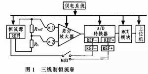
The temperature measuring system uses a three-wire constant current source driving method to drive the platinum resistance sensor. The three-wire constant current source driving method refers to the elimination of the fixed resistance (zero degree resistance) of the platinum resistance sensor by a hardware circuit, and directly measures the resistance variation of the sensor. Figure 1 is a high-precision measurement scheme of a three-wire constant current source driving method. The reference resistor is connected in series with the sensor and driven by a constant current source, and the components of the circuit will generate corresponding voltages. The voltage of the sensor due to temperature change can be directly measured by the following amplifier circuit and A/D converter, and the voltage measurement is used twice - the direction of the drive current is exchanged and measured once in each current direction. Its characteristic is to directly measure the resistance change of the sensor. The A/D converter utilizes high efficiency, and the output voltage of the circuit is linear with the change of resistance. The sensor uses a three-wire connection to effectively eliminate the effects of wire resistance and self-heating effects. Using the single-chip microcomputer system to control the two measurement voltages can avoid the system error caused by the wiring barrier voltage and the offset and drift of the amplifier and A/D converter, and can also calibrate the accuracy of the platinum resistance sensor. Constant current source and A/D converter share reference standard, so according to the measurement ratio conversion principle of A/D converter, the error caused by the instability of reference reference reference can be eliminated, but the constant current source is highly demanded and the circuit structure is complex. In order to further overcome the influence of noise and random error on measurement accuracy and stability, the MLS numerical algorithm is finally used in the host computer to achieve noise cancellation, which greatly improves the accuracy and stability of temperature measurement.
2. System circuit design
2.1 Three-wire constant current source drive circuit
The constant current source driving circuit is responsible for driving the temperature sensor Pt1000 to convert its sensed temperature-varying resistance signal into a measurable voltage signal. In this system, the constant current source required has a constant output current, good temperature stability, and large output resistance. The output current is less than 0.5 mA (the upper limit of Pt1000 has no self-heating effect), the load is grounded at one end, and the polarity of the output current can be changed.
Since the influence of temperature on the integrated operational amplifier parameters is not as significant as that of the transistor or FET parameters, the constant current source composed of the integrated operational amplifier has the advantages of better stability and higher constant current performance. Especially in the case where the load end needs to be grounded, it has been widely used. Therefore, the dual op amp constant current source shown in Figure 2 is used. The amplifier UA1 constitutes an adder, UA2 constitutes a follower, and UA1 and UA2 select a low noise, low offset, high open loop gain bipolar operational amplifier OP07.
Let the potentials at the upper and lower ends of the reference resistor Rref in Fig. 2 respectively Va and Vb, Va is the output of the in-phase adder UA1. When the resistor R1=R2 and R3=R4, then Va=VREFx+Vb, so the output current of the constant current source is:
It can be seen that the dual op amp constant current source has the following remarkable features:
1) The load can be grounded;
2) When the op amp is powered by dual power supplies, the output current is bipolar;
3) The constant current magnitude is achieved by changing the input reference reference VREF or adjusting the reference resistor Rref0. It is easy to obtain stable small current and compensated calibration.
Due to the mismatch of the resistor, the voltage across the reference resistor Rref0 will be affected by the terminal voltage Vb of its driving load. At the same time, because it is a constant current source, Vb will definitely change with the load, which will affect the stability of the constant current source. Obviously this is unacceptable for high precision constant current sources. Therefore, the selection principle of the four resistors R1, R2, R3, and R4 is that the mismatch should be as small as possible, and the mismatch size of each pair of resistors should be the same. In practice, a large number of precision resistors of the same batch can be screened, and four resistors with similar resistance values are selected.
2.2 Signal Conditioning Circuit
The signal conditioning circuit is shown in Figure 3. The amplifier UA3 unit-amplifies the terminal voltage of the reference resistor Rref to obtain a differential amplifier inverting input signal. Its value is:
The amplifier UA4 amplifies the terminal voltage of the temperature sensor Rt (PT1000) by 2 times to obtain the forward input signal of the differential amplifier. Its value is:
Among them, the selection principle of the resistors R5 and R6 is the same as the principle of selecting the proportional resistance in the previous constant current source analysis, that is, by screening a large number of common nominal resistors, the closest resistance is selected.
2.3 A / D conversion circuit
The A/D conversion circuit is implemented by an integrated A/D converter AD7712, which will also perform differential amplification of the instrumentation amplifier using its internal PGA. The AD7712 is a high precision A/D converter suitable for low frequency measurements. The chip contains two input channels, AIN1 and AIN2, which convert the analog signal into a serial data output. The principle circuit of data conversion acquisition using AD7712 is shown in Figure 4. It needs to be configured during actual work. The differential input channel AIN1 is selected and the input signal polarity is bipolar.
The error of the measurement result mainly comes from the error of the reference resistors Rref and Rref0, and the error of the differential amplification factor k and the conversion output of the A/D converter. In order to achieve the required measurement accuracy, the reference resistors Rref, Rref0 will use a custom UPR plastic foil foil resistor, which has an O. 05% initial accuracy, less than 5 ppm temperature stability. The nonlinear error of AD7712 is less than O. 001 5%, gain temperature stability is less than 2 ppm. And the AD7712 can be calibrated by a single-chip microcomputer to reduce its nonlinear error and gain error.
3 Calibration and measurement results
3.1 Measurement system calibration
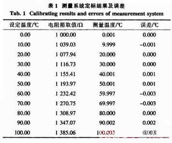
The measurement system was first calibrated using a high-precision resistor box (error 5 ppm) instead of the Pt1000. According to the measured Pt1000 resistance/temperature relationship calibration data shown in Equation 2, the corresponding test temperature point nominal value is set by changing the value of the resistance box. After measuring system, A/D sampling and PC program calculation, the measured temperature display value is obtained. According to the initial measurement data, the measurement circuit and the compensation voltage are calibrated, and the calibration data of the measurement system is obtained as shown in Table 1.
It can be seen from the measurement data of Table 1 that the maximum error introduced by the measurement system is 0.003 °C. Therefore, as long as the calibration error of the Pt1000 platinum resistance is small enough and the precision is high, the entire temperature measurement system can meet the high-precision measurement requirements.
3.2 Measurement of thermostat
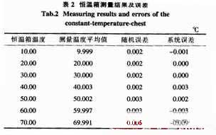
The platinum resistance sensor Pt1000 is connected to the measurement system and placed in a high-precision incubator (temperature control accuracy 0.01 °C) for calibration of the entire temperature measurement system. Pay attention to the seal of the incubator when measuring to improve the stability of the ambient temperature; After the temperature of the incubator is stable, 20 measurements are taken at the same temperature point every 3 minutes. The measured temperature value data and the processing results are shown in Table 2. Due to equipment conditions, the measurement temperature range is only (10 ~ 70 ° C).
3.2 Measurement of thermostat
The platinum resistance sensor Pt1000 is connected to the measurement system and placed in a high-precision incubator (temperature control accuracy 0.01 °C) for calibration of the entire temperature measurement system. Pay attention to the seal of the incubator when measuring to improve the stability of the ambient temperature; After the temperature of the incubator is stable, 20 measurements are taken at the same temperature point every 3 minutes. The measured temperature value data and the processing results are shown in Table 2. Due to equipment conditions, the measurement temperature range is only (10 ~ 70 ° C).
In Table 2, the random error is the standard deviation calculated from 20 measurements of the same temperature point (σ=SQR[(xi-X)2/(n-1)]); The systematic error is the difference between the set temperature of the oven and the average value of the temperature measured by the temperature measuring system. As can be seen from the data in Table 2, the maximum random error of the measurement system is 0.005 ° C, and is the smallest when it is close to room temperature; The maximum system error of the measurement system is -0.009 °C, which indicates that the calibration error of Pt1000 platinum resistance sensor is small and the precision is high, which can meet the measurement requirements of high precision temperature measurement system. However, the high temperature error is large, which may be related to the temperature control accuracy of the oven, which needs further calibration.
4. In conclusion
The Pt1000 platinum resistance is driven by a three-wire constant current source, which effectively overcomes the influence of wire resistance and self-heating effect on measurement accuracy; Using the single-chip microcomputer to calculate the two measured voltages under the bipolar driving current can effectively avoid the systematic error caused by the wiring barrier voltage and the offset and drift of the amplifier and A/D converter; The constant current source and the A/D converter share a reference reference, which effectively eliminates the error caused by the instability of the reference reference. The MLS numerical algorithm is used to cancel the noise in the host computer, which further overcomes the influence of noise and random error on measurement accuracy and stability, and greatly improves the temperature measurement accuracy and stability. The maximum measurement error of the whole machine is not more than 0.01 °C.


