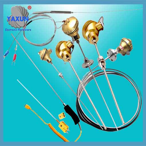
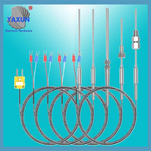
What is the RTD temperature sensor?
- PRODUCT DETAIL
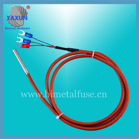
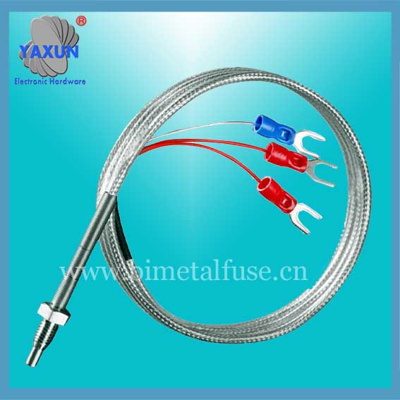
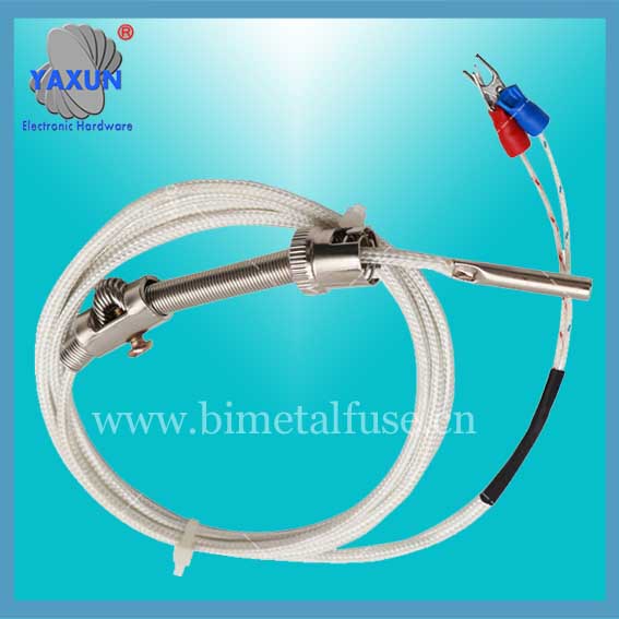
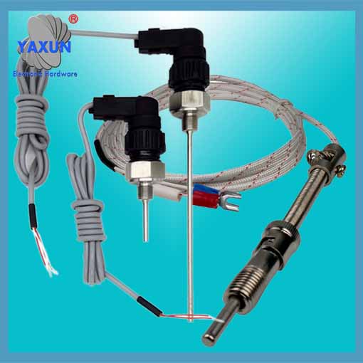
The thermal resistance temperature sensor has platinum thermal resistance and copper thermal resistance. The thermal resistance temperature sensor is a kind of sensor thermometer that uses the principle that the resistance value of a conductor or a semiconductor changes with temperature to measure temperature.
RTD temperature sensors are divided into two categories: metal thermal resistance and semiconductor thermistor. Thermal resistance is widely used to measure the temperature in the range of -200~+850°C. In a few cases, the low temperature can be measured up to 1K, and the high temperature can reach 1000°C.
The thermal resistance sensor is composed of thermal resistance, connecting wire and display instrument. The thermal resistance can also be connected with a temperature transmitter to convert the temperature into a standard current signal output.
The material used to make the thermal resistance should have as large and stable temperature coefficient of resistance and resistivity as possible, the output is best to be linear, the physical and chemical properties are stable, and the complex linearity is good.
There are three main ways for the lead of the national standard RTD sensor
Thermal resistance is a primary element that converts temperature changes into resistance changes. Usually the resistance signal needs to be transmitted to the computer control device or other primary instruments through the lead. Industrial thermal resistance is installed at the production site, and there is a certain distance between it and the control room, so the lead of the thermal resistance will have a greater impact on the measurement results.
There are three main ways to lead the national standard thermal resistance
2-wire RTD temperature sensor: The method of connecting a wire at both ends of the thermal resistance to lead out the resistance signal is called a two-wire system. This lead method is very simple, but because the connecting wire must have lead resistance r, the size of r is related to the material and length of the wire, so this lead method is only suitable for occasions with low measurement accuracy
3-wire thermal resistance sensor:
The method of connecting one lead at one end of the root of the thermal resistance and connecting two leads at the other end is called a 3-wire system. This method is usually used in conjunction with the electric bridge, which can better eliminate the influence of lead resistance, and is the most commonly used in industrial process control.
4-wire thermal resistance sensor:
The method of connecting two wires at both ends of the root of the thermal resistance is called a four-wire system. Two of the leads provide a constant current I for the thermal resistance, convert R into a voltage signal U, and then lead U to the secondary instrument through the other two leads. It can be seen that this lead method can completely eliminate the influence of lead resistance and is mainly used for high-precision temperature detection.
The thermal resistance sensor adopts the three-wire connection method. The three-wire system is used to eliminate the measurement error caused by the resistance of the connecting wire. This is because the circuit for measuring thermal resistance is generally an unbalanced bridge. The thermal resistance serves as a bridge arm resistance of the electric bridge, and its connecting wire (from the thermal resistance to the central control room) also becomes a part of the bridge arm resistance. This part of the resistance is unknown and changes with the ambient temperature, causing measurement errors. Using a three-wire system, one wire is connected to the power supply end of the bridge, and the other two wires are respectively connected to the bridge arm where the thermal resistance is located and the adjacent bridge arm. This eliminates the measurement error caused by the wire line resistance.
Selection data of thermal resistance sensor
Model, graduation number, temperature measurement range ℃, number of temperature measurement points, protection tube material
WRN-230D K 0-1000 2-12 GH3030
0-800 1Ci18Ni9Ni
WRE-230D E 0-600 1Ci18Ni9Ni
WRN-430D K 0-1000 GH3030
0-800 1Ci18Ni9Ni
WRE-430D E 0-600 Ci18Ni9Ni
1) Thermocouple Class I is ordered according to agreement;
2) The remaining materials of the protection tube are ordered according to the agreement;
3) External protection tube users should prepare their own
Installation fixed form:
Fixed thread
Number of temperature measurement points M D D H h SW d
2—6 M27x2 ¢40 ¢105 28 5 32 ¢20
7-12 M33x2 ¢48 ¢115 33 5 36 ¢34
Fixed flange:
Number of temperature measurement points D D1 D2 H do d
2—6 ¢105 ¢75 — 5 32 ¢20
7—12 ¢115 ¢85 — 5 36 ¢34
Selection instructions for thermal resistance sensors:
1) Model
2) Index number
3) Accuracy level
4) Number of thermocouple points
5) Installation and fixed form
6) Protection tube material
7) Length or insertion depth
Example: Multipoint thermocouple, type K, 3 points. L grade, fixed thread M27X2, L 1 = 1200, L 2 =1500, L 3 =2000, WRN-220D3I grade L 1 =1200, L 2 =1500, L 3 =2000, thread M27x2

