What is a Thermoelectric sensor?
Experimental purpose:
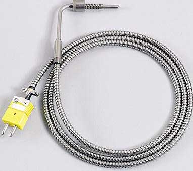
1. Observe the structure of the thermocouple, familiarize yourself with the working characteristics of the thermocouple, and learn to consult the thermocouple indexing table.
2. Understand the principle and operation of the PN junction temperature sensor.
3. Learn about NTC (negative temperature coefficient) thermistor phenomena and characteristics.
Second, the experimental principle:
Thermocouples, thermistors, and PN junction temperature sensors are typical pyroelectric sensors.
The basic working principle of a thermocouple is the thermoelectric effect. When the temperature of the hot end and the cold end are different, a thermoelectromotive force is generated. By measuring this electromotive force, the temperature difference between the two ends can be known. If the temperature at one end is fixed (generally the fixed cold end is room temperature or 0 ° C), the temperature at the other end can be known to achieve temperature measurement. In the CSY type.CSY10.CSY10A type tester, the thermocouple is copper-constantan (T-index), and the CSY10B type is nickel-chromium-nickel-silicon (K-index).
The semiconductor PN junction has very good temperature linearity. According to the PN junction characteristic expression formula (
 ), when a PN junction is formed, its reverse saturation current is basically only related to temperature. The PN junction integrated temperature sensor made according to this principle can directly display the absolute temperature K and has good linearity and precision.
Thermistors made of semiconductor materials have high sensitivity and can be applied to various fields. The thermocouple generally has a good linearity when measuring high temperature, and the thermistor is convenient for the temperature below 200 °C. The thermistor used in this experiment is a negative temperature coefficient. The change in the resistance value of the thermistor when the temperature changes causes the output voltage of the voltage/resistance conversion circuit composed of the operational amplifier to change accordingly.
Third, the components required for the experiment:
Thermocouples, heaters, differential amplifiers, voltmeters, thermometers, PN junction integrated temperature sensors, temperature converters, thermistors.
Fourth, the experimental steps:
1. Thermocouple experimental steps:
1) Turn on the power and zero the differential amplifier.
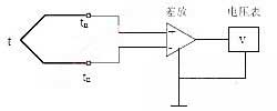
2) The differential amplifier double-ended input is connected to the thermocouple. As shown in Figure 11, turn on the heating switch and quickly zero the differential amplifier output (adjust the differential amplifier zero knob).
3) As the heater temperature rises, observe the change in the output voltage of the differential amplifier. When the heating temperature does not rise any more (to the relative thermal stability state), record the voltmeter reading.
4) The thermocouple on this instrument is made up of two copper-constantan thermocouples in series (the CSY10B experimental instrument is a K-index thermocouple). The cold junction temperature of the thermocouple is room temperature, and the gain of the amplifier is 100 times. Both should be taken into account when calculating the thermoelectric potential. Use a thermometer to read the room temperature tn at which the thermocouple reference is placed.
E(t , to) = E(t , tn) + E(tn , to)
Actual electromotive force = measured potential + temperature corrected electromotive force
Where E is the electromotive force of the thermocouple, t is the thermocouple hot end temperature, to is the thermocouple reference junction temperature is 0 ° C, and tn is the temperature at which the thermocouple reference end is located. Check the copper-constantan thermocouple indexing table or the nickel-chromium-nickel silicon thermocouple indexing table to find the heating end temperature t.
2. PN junction temperature sensor steps:
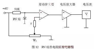
1) Wire the PN junction temperature sensor as shown in Figure 12.
2) Turn on the heater and observe the change in the voltage representation when the temperature rises; Turn off the heater to stop heating, and observe the change in voltage when the temperature is lowered. Record the above observations and analyze the cause according to the circuit.
3. NTC (negative temperature coefficient) thermistor experimental steps:
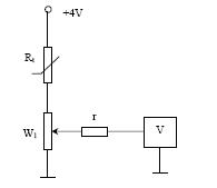
1) Observe the thermistor mounted in the envelope on the cantilever beam and line the thermistor as shown in Figure 13.
2) Turn on the heater and observe the temperature rise and temperature drop of the temperature converter voltmeter output. Record the above and analyze the cause according to the circuit
 Five, note:
1. Before the experiment, check whether the experimental patch cord is intact. When connecting the circuit, try to use a shorter patch cord to avoid introducing interference.
2. Plug the patch cord into the jack to ensure good contact. Do not pull the tail of the patch cord forcefully to avoid breaking the wire inside the cable.
3. Do not short-circuit the regulated power supply to the ground. The ground of all unit circuits must be connected to the power ground.
4. Because the differential amplifier amplification factor is ≈100 times in the instrument, the thermoelectric potential amplified by the differential amplifier is not very accurate, so the hot end temperature obtained by looking up the table is also an approximation.
5. The three-and-a-half digital voltmeter must be in 2V.
Sixth, thinking:
1. Try to analyze the error source of the PN junction temperature measurement circuit.
2. Why use cold junction compensation when using thermocouple temperature measurement?
3. What are the cold end compensation methods?


