PTC Resettable Fuses Selection Guide
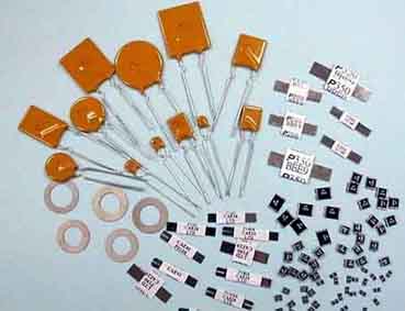
PTC (Polymer Positive Temperature Coefficient) devices help protect against overcurrent surges and overtemperature faults. Thermistor-type devices limit dangerous high currents under fault conditions.
But it is different from the traditional fuse can only be used once and must be replaced. YAXUN's carefully crafted PTC devices can be reset after troubleshooting and disconnecting power, reducing component cost, service and maintenance costs.
The PTC circuit protection device is made of a polymer PTC material mixed with nano-conductor particles. At normal temperatures, the material tightly binds the conductor to the crystalline structure, forming a low-impedance link.
However, when a large current passes or the ambient temperature rises and the device temperature is higher than the operating temperature, the conductor in the polymer melts and becomes irregularly arranged, and the volume expands and causes the impedance to increase rapidly.
Polymer PTC for overcurrent protection
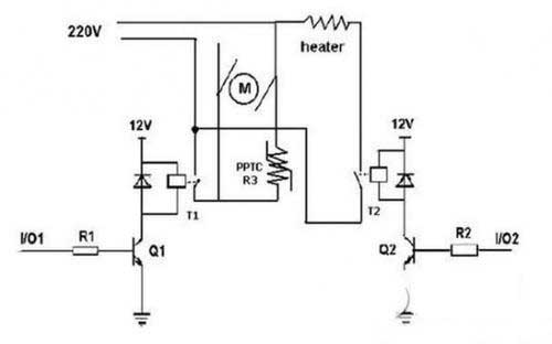
The positive temperature coefficient (PTC) overcurrent protection device is used in series in the circuit. When the current increases rapidly, PTC changes from low resistance to high resistance to protect the circuit. This is called device 'action'.
In normal operation, the resistance of this device is much smaller than the rest of the resistors in the circuit. However, in response to an overcurrent condition, the device resistance is increased (acting), thereby reducing the current in the circuit to a value that can be safely carried by any circuit device. This protection action is caused by the heat generated by the internal I2RT or the high temperature of the device around the PTC, which causes the device temperature to rise rapidly.
The principle of action of a PTC device is a balance of energy. When current flows through the PTC device, heat is generated due to the relationship of I2RT, and the generated heat is completely or partially emitted to the environment. If it is not emitted, the temperature of the PTC device is increased.
PTC selection method and steps
Step 1: Determine the circuit parameters
You need to determine the following parameters of the circuit:
Maximum working environment temperature
Standard operating current
Maximum operating voltage
Maximum interrupt current
Step 2: Select a PTC device that can accommodate the maximum ambient temperature and standard operating current of the circuit
Use the reduction ratio (ambient temperature (℃) to maintain the current (A)] meter and select the temperature that best matches the maximum ambient temperature of the circuit. Browse this column to see values equal to or greater than the standard operating current of the circuit. Now look at the far left of the line and look at the device family that best fits the circuit.
Step 3: Compare the maximum electrical rating of the selected device to the maximum operating voltage and interrupt current of the circuit
Use the electrical characteristics table to verify that the part you selected in step 2 will use the maximum operating voltage and interrupt current of the circuit. Check the maximum operating voltage (Vmax) and maximum interrupt current (Imax) of the device. Make sure that Vmax and Imax are greater than or equal to the maximum operating voltage and maximum interrupt current of the circuit.
Step 4: Determine the action time
The action time is the amount of time it takes for the device to switch to a high resistance state when a fault current passes through the device. In order to provide the desired protection function, it is important to clarify the operating time of the PTC device. If the device you selected moves too fast, there may be abnormal actions or malfunctions. If the device is moving too slowly, the protected device may be damaged before the device can act and limit the current.
A typical operating time curve at 25 °C is used to determine whether the PTC device's operating time characteristics are acceptable at the expected fault current. If not, go back to step 2 and select another replacement device.
Step 5: Verify ambient operating temperature
Ensure that the minimum and maximum ambient temperatures for the application are within the operating temperature range of the PTC device. Most PTC devices have an operating temperature range of -40°C to 85°C and, in some special cases, 125°C.
Step 6: Verify the form factor of the PTC device
Use a form factor table to compare the form factor of your chosen PTC device to the space conditions of your application.
Parameter definition description:
IH: Maximum operating current at 25 ° C ambient temperature
IT: Minimum current for PTC device action protection at 25°C ambient temperature
Vmax: Maximum operating voltage for safe disconnection of PTC devices
Imax: Maximum fault current for safe operation of PTC devices at 25 °C ambient temperature
Rmax: Initial maximum resistance before PTC device is not operated at 25 °C ambient temperature
Rmin: Initial minimum resistance before PTC device is not operated at 25 °C ambient temperature
But it is different from the traditional fuse can only be used once and must be replaced. YAXUN's carefully crafted PTC devices can be reset after troubleshooting and disconnecting power, reducing component cost, service and maintenance costs.
The PTC circuit protection device is made of a polymer PTC material mixed with nano-conductor particles. At normal temperatures, the material tightly binds the conductor to the crystalline structure, forming a low-impedance link.
However, when a large current passes or the ambient temperature rises and the device temperature is higher than the operating temperature, the conductor in the polymer melts and becomes irregularly arranged, and the volume expands and causes the impedance to increase rapidly.
Polymer PTC for overcurrent protection
The positive temperature coefficient (PTC) overcurrent protection device is used in series in the circuit. When the current increases rapidly, PTC changes from low resistance to high resistance to protect the circuit. This is called device 'action'.
In normal operation, the resistance of this device is much smaller than the rest of the resistors in the circuit. However, in response to an overcurrent condition, the device resistance is increased (acting), thereby reducing the current in the circuit to a value that can be safely carried by any circuit device. This protection action is caused by the heat generated by the internal I2RT or the high temperature of the device around the PTC, which causes the device temperature to rise rapidly.
The principle of action of a PTC device is a balance of energy. When current flows through the PTC device, heat is generated due to the relationship of I2RT, and the generated heat is completely or partially emitted to the environment. If it is not emitted, the temperature of the PTC device is increased.
PTC selection method and steps
Step 1: Determine the circuit parameters
You need to determine the following parameters of the circuit:
Maximum working environment temperature
Standard operating current
Maximum operating voltage
Maximum interrupt current
Step 2: Select a PTC device that can accommodate the maximum ambient temperature and standard operating current of the circuit
Use the reduction ratio (ambient temperature (℃) to maintain the current (A)] meter and select the temperature that best matches the maximum ambient temperature of the circuit. Browse this column to see values equal to or greater than the standard operating current of the circuit. Now look at the far left of the line and look at the device family that best fits the circuit.
Step 3: Compare the maximum electrical rating of the selected device to the maximum operating voltage and interrupt current of the circuit
Use the electrical characteristics table to verify that the part you selected in step 2 will use the maximum operating voltage and interrupt current of the circuit. Check the maximum operating voltage (Vmax) and maximum interrupt current (Imax) of the device. Make sure that Vmax and Imax are greater than or equal to the maximum operating voltage and maximum interrupt current of the circuit.
Step 4: Determine the action time
The action time is the amount of time it takes for the device to switch to a high resistance state when a fault current passes through the device. In order to provide the desired protection function, it is important to clarify the operating time of the PTC device. If the device you selected moves too fast, there may be abnormal actions or malfunctions. If the device is moving too slowly, the protected device may be damaged before the device can act and limit the current.
A typical operating time curve at 25 °C is used to determine whether the PTC device's operating time characteristics are acceptable at the expected fault current. If not, go back to step 2 and select another replacement device.
Step 5: Verify ambient operating temperature
Ensure that the minimum and maximum ambient temperatures for the application are within the operating temperature range of the PTC device. Most PTC devices have an operating temperature range of -40°C to 85°C and, in some special cases, 125°C.
Step 6: Verify the form factor of the PTC device
Use a form factor table to compare the form factor of your chosen PTC device to the space conditions of your application.
Parameter definition description:
IH: Maximum operating current at 25 ° C ambient temperature
IT: Minimum current for PTC device action protection at 25°C ambient temperature
Vmax: Maximum operating voltage for safe disconnection of PTC devices
Imax: Maximum fault current for safe operation of PTC devices at 25 °C ambient temperature
Rmax: Initial maximum resistance before PTC device is not operated at 25 °C ambient temperature
Rmin: Initial minimum resistance before PTC device is not operated at 25 °C ambient temperature


