Overcurrent protection design method for DC circuits
Electronic protection circuit has the characteristics of high-speed current cut-off and easy recovery. It can be used as over-current protection device in any DC circuit. However, the protection circuit using the common fuse has a slower overcurrent response and cannot be used as a sensitive protection device.
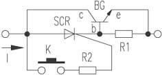
Principle: The electronic protection circuit is shown in the drawing. When the micro switch K is turned on, the unidirectional thyristor SCR is turned on, and the direct current circuit is also turned on. When the power consumption increases beyond the specified allowable value, when the voltage across the sense resistor R1 is greater than 0.7V, the transistor BG is turned on. At this time, the voltage between the collector C and the base b of the transistor falls below the sustain voltage of 3CT, and the 3CT is turned off, and the power supply circuit is turned off.
Component selection: When the voltage across the circuit is ≤100V, BG uses 3DD15C, and unidirectional thyristor SCR can use 6A/400V. The resistance of R1 is determined according to the current allowed by the power supply, that is, R1=0.7/I (I is the power supply allowable current). If the power consumption of the circuit is 5W, the resistance of R2 is 0.35Ω, and the current allowed to pass is 2A.
Component selection: When the voltage across the circuit is ≤100V, BG uses 3DD15C, and unidirectional thyristor SCR can use 6A/400V. The resistance of R1 is determined according to the current allowed by the power supply, that is, R1=0.7/I (I is the power supply allowable current). If the power consumption of the circuit is 5W, the resistance of R2 is 0.35Ω, and the current allowed to pass is 2A.


