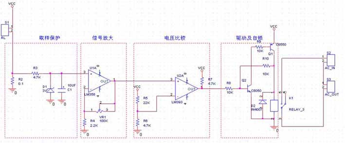
Overcurrent protection circuit with self-locking
1. The first part is the resistance sampling, the load and R1 are connected in series, as we all know. The currents in series are equal. The voltage on R2 changes with the current of the load, the current is large, and the voltage across R2 is also high. R3 D1 constitutes an op amp protection circuit to prevent excessive voltage from entering the op amp and causing damage to the op amp. C1 is used to prevent interference.
2. The second part is a phase-in-phase amplifier that everyone is quite familiar with. Since the signal of the resistance sampling of the previous stage is small, it is necessary to use an amplification circuit to amplify. Can be used, the magnification is determined by VR1 R4.
3. The third part is a comparator circuit, the amplifier amplifies the sampled signal, and then through this level of comparison, to control the action of the latter stage, whether to cut off the power or other operations, the comparator is an open output. So add the upper resistor, or you can't output a high level.
4. The fourth part is a circuit that drives the relay. This circuit is different from the general one. This is a self-locking circuit. After a protection signal comes in, the circuit will work until it is turned off and then turned on. This self-locking circuit structure is similar to a unidirectional thyristor.


