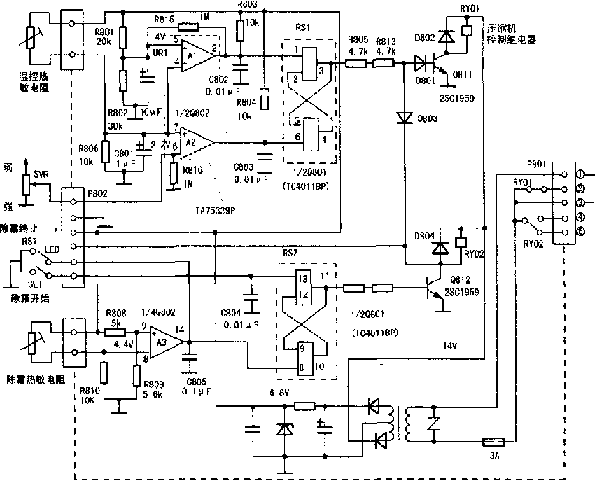
NTC temperature control circuit diagram of a sensor used in refrigerators

The three op amps (A1, A2, A3) in the TA75339P (Q802) are connected to three voltage comparators to detect the change in resistance of the temperature-controlled thermistor.
A1's non-inverting input terminal 5 has a 4V reference voltage UR1, and its inverting input terminal 4 has a temperature-sensing thermistor and a temperature sensing component consisting of R806.
When the temperature inside the refrigerator rises to a certain value (about 3.5 ° C), the resistance of the temperature-controlled thermistor drops (about 6.7 kΩ). The 4 pin voltage rises (about 1V), and the A1 output pin 2 goes low.
This low level is applied to the RS11 pin, so that the 3 pin is high and the compressor is turned on.
Comparator A2 has an adjustable reference voltage UR2 at the inverting input terminal 6 and a maximum voltage of approximately 2.2V (approximately 1.5V when adjusted to the "winter" side).
The 7-pin of the non-inverting input of A2 is also connected to the temperature-controlled thermistor.
After starting for a period of time, the temperature inside the box drops, the resistance of the temperature-controlled thermistor becomes larger, and the voltage of the 7-pin decreases.
When the reference voltage UR2 set below the 6 pin is set, the output pin 1 of A2 becomes a low level. This low level is added to the 6 pin of the RSI, so that the 3 pin of the RS1 output terminal is low level, and the compressor is stopped, thereby realizing the automatic temperature control function.
A3 and RS2 complete the semi-automatic defrost control function, and its non-inverting input terminal 9 has a reference voltage of about 4.4V (divided by R808 and R809). The inverting input terminal 8 is connected to a voltage divider composed of a defrosting thermistor and an R810.
After the defrosting starts, the temperature inside the refrigerator gradually rises. When it rises to about 8.5 °C, the resistance of the defrosting thermistor drops (about 5.4kΩ), and the voltage of the 8-pin gradually rises. When the 4.4V is higher than the 9th pin, the A3 output terminal 14 is changed from the high level to the low level, the Q812 is cut off, and the defrosting is terminated.
When pressing the "Defrost Termination" button on the panel, input a low level directly to the RS28 pin, or force the defrost to be aborted.
When the control function is not normal, try to unplug the temperature control thermistor. At this time, A15 pin and A27 pin are all low level, so A12 pin should be high level, and A21 pin should be low level; Otherwise, the TA75339P is damaged (peripheral components are good). Remove the TA75339P and check the TC4011BP. the way is: Connect the multimeter (set voltage) to the RSl output 3 and the ground, and short the 6 feet to the ground. If it is normal, the 3 feet should be low; Then try to short the 1 foot to the ground, 3 feet should be high; otherwise, TC4011BP is damaged.


