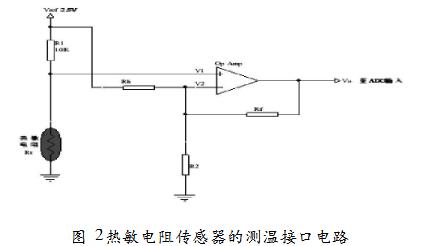
Measurement Interface Circuit of Thermistor Sensor

Figure 1 Measurement interface circuit
Figure 1 shows the interface circuit of the thermistor sensor using the in-phase amplifier circuit for temperature measurement. The interface circuit uses a resistor to linearize the thermistor sensor, and the interface circuit has a voltage mode and a resistance mode. The role of both is to achieve linearization. Figure 2 shows the linearization with a fixed resistor R1, called the voltage mode.
Resistor R1 pulls the thermistor's voltage up to the reference voltage, which is generally consistent with the ADC's reference voltage, so if the ADC's reference voltage is 5V, Vref will also be 5V. The thermistor and the resistor are connected in series to generate a partial voltage, and the resistance change causes the voltage V1 at the node to also change. The accuracy of this circuit depends on the error of the thermistor and resistor and the accuracy of the reference voltage.


