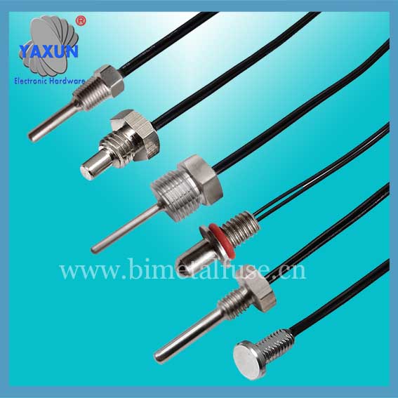
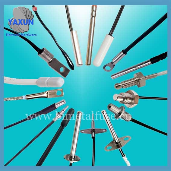
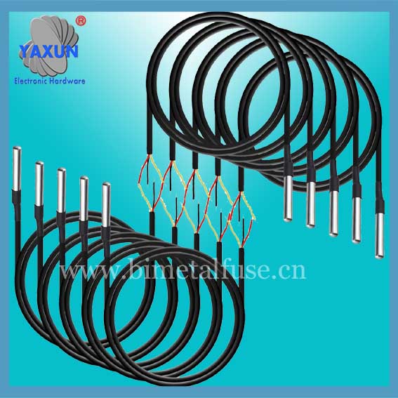
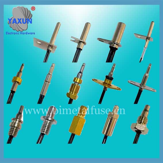
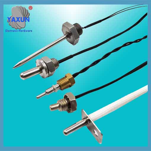
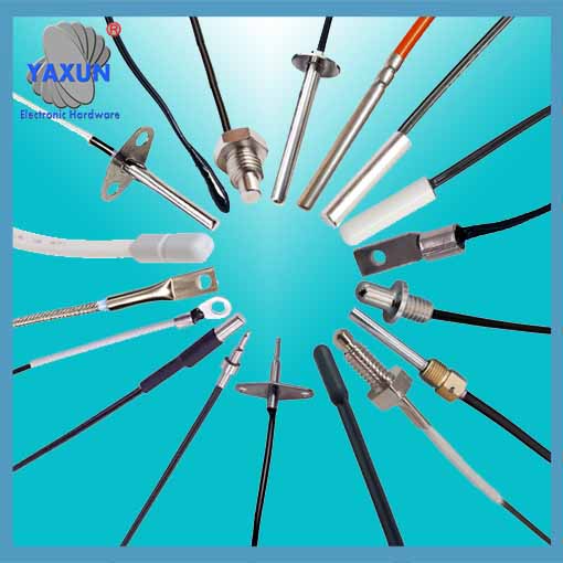
Machining Induction Cooker High Precision Temperature Sensor
- PRODUCT DETAIL
As everyone knows, the induction cooker, as a popular household kitchenware, not only has the function of heating, but also has many automatic functions. For example, automatic heat preservation, automatic boiling water, automatic rice cooking, automatic soup cooking and other functions. The realization of all these automatic functions requires the induction cooker to be able to accurately measure and control the temperature. The existing induction cooker mainly uses a temperature sensor for temperature measurement. Such as
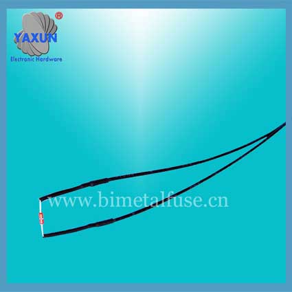
As shown in FIG. 1, it is a schematic structural diagram of a conventional induction cooker temperature sensor having a probe 2 for contacting the induction cooker panel 1. The probe 2 is a thermal sensitive device such as a thermal resistor. A rubber seat 3 made of a heat-insulating material fixes the probe 2 on the top. Then, the rubber base 3 is installed in the center of the induction cooker panel 1, so that the probe 2 is fully in contact with the induction cooker panel 1, and the lead 4 is also led out of the probe 2. The temperature signal is transmitted to the microprocessor of the induction cooker by the lead wire 4 for further processing. With this induction cooker temperature sensor, since the area of the probe 2 is limited, the contact area with the induction cooker panel 1 is also limited. In addition, since the shape of the contact portion of the induction cooktop plate 1 and the probe 2 may be uneven, it is not possible to guarantee complete contact between the two. Moreover, as the rubber base 3 ages during use, the possibility of incomplete contact increases, which causes the temperature measured by the probe 2 to be inconsistent with the actual temperature of the induction cooker panel 1, thereby affecting the use of the induction cooker.
The temperature sensor on the induction cooker is actually a semiconductor thermistor with a negative temperature coefficient. The resistance value will decrease as the temperature itself rises, and the temperature will rise, and the voltage across the resistance will change through the change in resistance. If it is not connected, the induction cooker will cause an alarm and it will be dangerous.
Generally, two types of resistors with the same specifications are used inside the induction cooker: One detects the furnace surface temperature, One detects the operating temperature of IBGT. When you open the top cover on the induction cooker, there is a circular element in the center of the base, which is the temperature sensor for the induction cooker.
The temperature control of the induction cooker is transmitted to the IC chip and converted to a temperature value according to the resistance value of the thermistor. In order to meet the different temperature heating methods. The other temperature sensor is fixed on the heat sink aluminum plate or squeezes the power tube. Of course, some temperature sensors are installed on the circuit board near the heat-dissipating aluminum plate, which looks the same as the middle under the panel.
Common troubleshooting methods of induction cooker:
1. The fan does not turn: Check the fan power supply and check whether the voltage at the 18V switching power supply is normal.
2. The fan has noise or rotates: Check if the CPU's crystal welding position is correct, and whether the pads are de-soldered.
3. Power is not adjustable: Check whether the CPU works normally (measure the voltage of the relevant pins), and see if the potentiometer (VR) on the motherboard that regulates the current is normal.
4. Start without heating: Check whether the temperature-sensitive thermistor is short-circuited, check whether the inductor L3 is soldered or damaged, and check whether multiple high-power resistors on the motherboard are damaged.

