Linearization Processing of Pt1000 Signal of WZP Platinum Resistance Temperature Sensor
The WZP type platinum resistance temperature sensor product Pt1000 is a device that detects temperature and temperature related parameters by utilizing the characteristics of the electromagnetic parameters of the components as a function of temperature. Because of its relatively good linearity, strong oxidation resistance, and wide temperature range, its temperature range is from -200 ° C to + 650 ° C. It is widely used in industrial production and scientific research. The signal processing circuit of the sensor product needs to complete the conversion of the temperature-dependent resistance change signal into a uniform voltage signal.
1. Pt1000 output characteristic curve
Put the Pt1000 into the high and low temperature experiment box, set the temperature to -30 °C ~ +70 °C, and measure the resistance value of the temperature sensor product at different temperatures. The measured data is shown in Figure 1. In the measured temperature range, the Pt1000 output resistance value is proportional to the temperature. However, under high temperature and low temperature conditions, there is a certain deviation, and temperature compensation is required in the conditioning circuit.
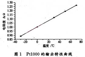
Figure 1. Pt1000 output characteristic curve
2. Basic constant current source circuit
The signal processing circuit of platinum resistance temperature sensor products can use constant voltage source or constant current source. Through the study of constant voltage source, it is found that there are problems such as instability and low precision in practical applications. The reason is that in the constant voltage operation, in addition to the nonlinear error of the platinum resistor itself, the inherent error of the constant voltage working circuit is generated, so that the systematic error of the whole circuit becomes large. Therefore, this paper uses a constant current source method. The basic constant current source circuit is shown in Figure 2. Replace the Rf of the inverting amplifier with a platinum resistor RT, which can be obtained according to the formula of the inverting amplifier:

Figure 2. Constant current source circuit diagram
Vi, after R1 is fixed, the current flowing through RT is constant, and Vo is proportional to RT. From the change of RT, the corresponding voltage change can be obtained, thereby achieving voltage output and the linearity remains unchanged.
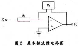
Basic constant current source circuit diagram
3. Temperature Processing Circuit with In-phase Input
The ideal temperature sensing circuit has an output voltage of 0 V at 0 °C, and RT=1 000.8 Ω in Figure 1, and the Vo obtained by substituting equation (1) is not 0, so the voltage needs to be zeroed. The method is implemented by adding an input voltage to the non-inverting terminal of the op amp in Figure 2, as shown in Figure 3.
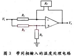
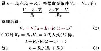
So as long as k can be adjusted to the appropriate value, the signal can be zeroed. But because this is only a theoretical calculation, the actual op amp is not ideal, and the resistance will not fully meet the nominal resistance due to the influence of temperature and the like. Therefore, the sizes of R2 and R3 are not fixed, and in practice, a variable resistor is used for fine adjustment.
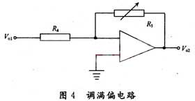
The adjustment of the non-inverting input voltage makes the output voltage decrease even if the temperature rises. Therefore, in order to ensure the linear output of the signal from -300 to 700 mV at -30 °C to +70 °C, an amplifying circuit is used after zeroing. Adjust the magnification factor. As shown in Figure 4.
Figure 4 shows the inverting amplifier circuit. It can not only realize the amplification effect of A=R5/R4, but also reverse the voltage Vo1 inverted by the previous stage op amp. Meet the required positive phase voltage.
4. Linearization supplementary processing
The relationship after the op amp 1 is shown in equation (2). After linear amplification of Operational Amplifier 2, if RT is certain, Vo is proportional to Vi, so to keep linear, Vi is best a fixed value, otherwise there will be two function values of Vi and RT in Vo's function relationship, which can not accurately measure temperature. The range of voltage fluctuation given by the design is (+10%VCC) and RT is fixed at a certain temperature. Then the final Vo also has (+10%) fluctuation. Using the unified R-T relationship to judge, the temperature error in the range of measurement becomes (+10%) which can not be tolerated. The circuit must have a reliable high-precision voltage regulator. Therefore, in the actual operation of the circuit, the high-precision voltage reference MAX6025 can be used to supply components and circuits with a high-precision voltage reference.
In addition, from the relationship between the Pt1000 platinum resistance value R and the temperature T, the Pt1000 has a high sensitivity of 3.786 59 Ω/°C in the measurement temperature range, so only a general-purpose operational amplifier is required. When the temperature coefficient of the resistor used is matched, the nonlinear error can be ignored.
5. Actual temperature sensing signal processing circuit
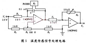
The actual temperature sensing signal processing circuit is shown in Figure 5. The capacitor C in the circuit diagram is the noise reduction capacitor. The actual value is 1μF. The 2.5V voltage reference is provided by the MAX6025. According to the parameters given in the figure, before performing the actual temperature test, it must first be zeroed and fully adjusted. Use a precision adjustable resistor instead of Pt1000 to connect to the circuit, change the resistance to equal the equivalent resistance of 0 000.8 Ω at 0 °C, adjust the variable resistor R5, so that the output voltage is 0. Then change the precision adjustable resistance value to 1 265.8 Ω at 70 °C, adjust the variable resistor R6, and make the output 700 mV, complete the zero adjustment and full adjustment. The circuit has been experimentally tested to achieve a good temperature sensing effect.
1. Pt1000 output characteristic curve
Put the Pt1000 into the high and low temperature experiment box, set the temperature to -30 °C ~ +70 °C, and measure the resistance value of the temperature sensor product at different temperatures. The measured data is shown in Figure 1. In the measured temperature range, the Pt1000 output resistance value is proportional to the temperature. However, under high temperature and low temperature conditions, there is a certain deviation, and temperature compensation is required in the conditioning circuit.

Figure 1. Pt1000 output characteristic curve
2. Basic constant current source circuit
The signal processing circuit of platinum resistance temperature sensor products can use constant voltage source or constant current source. Through the study of constant voltage source, it is found that there are problems such as instability and low precision in practical applications. The reason is that in the constant voltage operation, in addition to the nonlinear error of the platinum resistor itself, the inherent error of the constant voltage working circuit is generated, so that the systematic error of the whole circuit becomes large. Therefore, this paper uses a constant current source method. The basic constant current source circuit is shown in Figure 2. Replace the Rf of the inverting amplifier with a platinum resistor RT, which can be obtained according to the formula of the inverting amplifier:

Figure 2. Constant current source circuit diagram
Vi, after R1 is fixed, the current flowing through RT is constant, and Vo is proportional to RT. From the change of RT, the corresponding voltage change can be obtained, thereby achieving voltage output and the linearity remains unchanged.

Basic constant current source circuit diagram
3. Temperature Processing Circuit with In-phase Input
The ideal temperature sensing circuit has an output voltage of 0 V at 0 °C, and RT=1 000.8 Ω in Figure 1, and the Vo obtained by substituting equation (1) is not 0, so the voltage needs to be zeroed. The method is implemented by adding an input voltage to the non-inverting terminal of the op amp in Figure 2, as shown in Figure 3.


So as long as k can be adjusted to the appropriate value, the signal can be zeroed. But because this is only a theoretical calculation, the actual op amp is not ideal, and the resistance will not fully meet the nominal resistance due to the influence of temperature and the like. Therefore, the sizes of R2 and R3 are not fixed, and in practice, a variable resistor is used for fine adjustment.
The adjustment of the non-inverting input voltage makes the output voltage decrease even if the temperature rises. Therefore, in order to ensure the linear output of the signal from -300 to 700 mV at -30 °C to +70 °C, an amplifying circuit is used after zeroing. Adjust the magnification factor. As shown in Figure 4.
Figure 4 shows the inverting amplifier circuit. It can not only realize the amplification effect of A=R5/R4, but also reverse the voltage Vo1 inverted by the previous stage op amp. Meet the required positive phase voltage.

4. Linearization supplementary processing
The relationship after the op amp 1 is shown in equation (2). After linear amplification of Operational Amplifier 2, if RT is certain, Vo is proportional to Vi, so to keep linear, Vi is best a fixed value, otherwise there will be two function values of Vi and RT in Vo's function relationship, which can not accurately measure temperature. The range of voltage fluctuation given by the design is (+10%VCC) and RT is fixed at a certain temperature. Then the final Vo also has (+10%) fluctuation. Using the unified R-T relationship to judge, the temperature error in the range of measurement becomes (+10%) which can not be tolerated. The circuit must have a reliable high-precision voltage regulator. Therefore, in the actual operation of the circuit, the high-precision voltage reference MAX6025 can be used to supply components and circuits with a high-precision voltage reference.
In addition, from the relationship between the Pt1000 platinum resistance value R and the temperature T, the Pt1000 has a high sensitivity of 3.786 59 Ω/°C in the measurement temperature range, so only a general-purpose operational amplifier is required. When the temperature coefficient of the resistor used is matched, the nonlinear error can be ignored.

5. Actual temperature sensing signal processing circuit
The actual temperature sensing signal processing circuit is shown in Figure 5. The capacitor C in the circuit diagram is the noise reduction capacitor. The actual value is 1μF. The 2.5V voltage reference is provided by the MAX6025. According to the parameters given in the figure, before performing the actual temperature test, it must first be zeroed and fully adjusted. Use a precision adjustable resistor instead of Pt1000 to connect to the circuit, change the resistance to equal the equivalent resistance of 0 000.8 Ω at 0 °C, adjust the variable resistor R5, so that the output voltage is 0. Then change the precision adjustable resistance value to 1 265.8 Ω at 70 °C, adjust the variable resistor R6, and make the output 700 mV, complete the zero adjustment and full adjustment. The circuit has been experimentally tested to achieve a good temperature sensing effect.


