How to use the module's internal NTC to measure temperature values
The temperature of the chip is one of the most important parameters in the operation of power electronics. One possible way to measure the temperature of the chip is to measure the temperature of the substrate as the base data and then calculate the junction temperature through a thermal model. In many of Infineon's power modules, thermistors, also known as NTCs, are integrated inside the module as a temperature sensor for easy temperature measurement.
This article details the isolation measures and how to use NTC to measure temperature values.
Internal design
The NTC is mounted near the silicon chip to achieve a tight thermal coupling. Depending on the module, the NTC is either mounted on the same DCB as the silicon chip or mounted on a separate substrate.

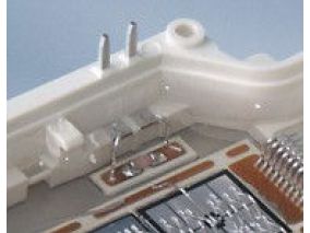
Figure 1 (a) EconoDUALTM 3 is mounted on the inside of the NTC separate DCB near the IGBT

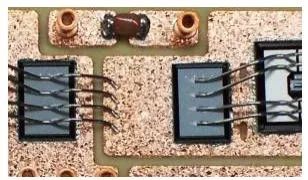
Figure 1(b) Module NTC without backplane, mounted near the silicon chip

This conductive path can be formed by the connection of the connection line when the fault occurs, or by the plasma path generated by the arc at the time of breakdown. For this reason, the insulation of the internal NTC is only a functional insulation, and if isolation is required, an external isolation barrier is required. Possible methods are:
- Use high voltage as the reference potential for the design control circuit and add an isolation barrier between the human contact and the control circuit. - Use an op amp with internal isolation to detect the voltage across NTC. - Use an isolation device such as a magnetic or optocoupler to convert the voltage of the NTC into a digital signal that can be transmitted to the control circuit.
NTC heat dissipation
The internal heat flow path of the module with built-in NTC is shown in Figure 3.


Two conclusions can be drawn:
1. The temperature of the thermistor TNTC will be lower than the junction temperature TJunction due to the temperature drop on the RthJNTC connecting the junction to the NTC.
2. For the same reason, the temperature of the NTC will be higher than the temperature measured on the heat sink.
It is known from experience that for power electronics, the difference between the temperature of the heat sink and the temperature of the NTC is approximately equal to 10K.
If you want to calculate a temperature value that cannot be directly measured, you must know the value of the Rth-chain on the heat conduction path. For a given module, the corresponding RthJC and RthCH of the IGBT and diode can be obtained from the data sheet.
IGBT value

Diode value

Figure 5 Rth values in the Infineon Power Electronics Module Data Sheet
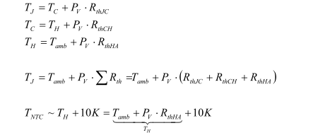
Based on the above values, the following formula can be used to simulate the temperature at each point:


among them:

For a smaller temperature range, the data sheet also provides values for B25/50 and B25/80 for more accurate calculations.
From the measured voltage UR, the actual resistance R(θ) can be calculated as:
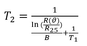
 Thus the expression of the actual temperature can be derived:

The UR values measured, the microprocessor using a simple equation can be solved to obtain the temperature value measured. If only a threshold signal of maximum temperature is required, it is sufficient to use a comparator that is triggered at a predetermined value.
The size of R1 in the voltage divider
The resistance of R1 should be carefully selected. If chosen too small, the power loss generated by the current flowing through the NTC will heat the NTC and change the measurement. On the other hand, if R1 is chosen too large, the measured voltage is too small, which will reduce the measurement accuracy.
In order to minimize the effects of current, it is necessary to analyze the thermal characteristics of NTC. The thermal conductivity of NTC is 145K/W. If the temperature is allowed to have a precision difference of 1K, the power loss inside the NTC cannot exceed Pmax = 6.9mW. Assuming that the temperature to be measured is 100 ° C, the resistance of NTC is R100 = 493 Ω.
It can be seen that the current maximum can be calculated as:

For the U1=5V supply voltage and the 3 mA current limit, the resistor R1 is:

Since there is no such nominal resistance, the resistance of 910Ω can be selected so that Imax=3.56mA; In the case where a 1K temperature deviation is allowed, any resistance that makes the current I < 4 mA can be selected.
Digitally measure NTC
In addition to the method of dividing the voltage, the resistance of NTC with temperature can also be used to influence the time constant of the R-C circuit. The basic circuit diagram is shown in Figure 7:

Figure 7 Basic schematic diagram of the temperature obtained by the digital method
The output of the comparator is changed by setting the threshold of the comparator by resistors R11 and R12. The output signal Uout is used to trigger transistor Q1 to discharge the capacitor. Since the charging of the capacitor is controlled by the resistance R(θ) of NTC, Uout is a pulse of frequency fout= g(θ).
In order to get the actual temperature value from Uout, it is only necessary to calculate the number of pulses in a fixed period. The correspondence between the number of pulses and the temperature can be obtained by using an analytical expression or by looking up a table. The value between the two calibration points can be derived by interpolation.
This article details the isolation measures and how to use NTC to measure temperature values.
Internal design
The NTC is mounted near the silicon chip to achieve a tight thermal coupling. Depending on the module, the NTC is either mounted on the same DCB as the silicon chip or mounted on a separate substrate.

Figure 1 (a) EconoDUALTM 3 is mounted on the inside of the NTC separate DCB near the IGBT

Figure 1(b) Module NTC without backplane, mounted near the silicon chip
Insulation isolation measures
Regardless of where the NTC is located, it is covered by silicone filled inside the module to meet the isolation requirements under normal operating conditions. If it fails, a conductive path will be generated between the high voltage side and the NTC. The conductive path is as shown in Figure 2:
Regardless of where the NTC is located, it is covered by silicone filled inside the module to meet the isolation requirements under normal operating conditions. If it fails, a conductive path will be generated between the high voltage side and the NTC. The conductive path is as shown in Figure 2:

figure 2 Conductive path when breakdown fails
This conductive path can be formed by the connection of the connection line when the fault occurs, or by the plasma path generated by the arc at the time of breakdown. For this reason, the insulation of the internal NTC is only a functional insulation, and if isolation is required, an external isolation barrier is required. Possible methods are:
- Use high voltage as the reference potential for the design control circuit and add an isolation barrier between the human contact and the control circuit. - Use an op amp with internal isolation to detect the voltage across NTC. - Use an isolation device such as a magnetic or optocoupler to convert the voltage of the NTC into a digital signal that can be transmitted to the control circuit.
NTC heat dissipation
The internal heat flow path of the module with built-in NTC is shown in Figure 3.

Figure 3 Heat flow inside the power electronics module
Most of the heat generated by the chip is dissipated directly into the environment through the heat sink. In addition, a portion of the heat is conducted through the DCB substrate and backplane to the location where the NTC is located. Since the heat cannot flow instantaneously, the NTC is only suitable for measuring the temperature at which the module operates in steady state. Because the associated time constant is too small, some transient phenomena, such as the instantaneous heat generated during a short circuit, cannot be monitored.
An important conclusion is that NTC cannot be used for short circuit protection!
The equivalent thermal path of the heat conduction path is shown in Figure 4:
An important conclusion is that NTC cannot be used for short circuit protection!
The equivalent thermal path of the heat conduction path is shown in Figure 4:

Figure 4 Schematic diagram of the equivalent thermal path
Two conclusions can be drawn:
1. The temperature of the thermistor TNTC will be lower than the junction temperature TJunction due to the temperature drop on the RthJNTC connecting the junction to the NTC.
2. For the same reason, the temperature of the NTC will be higher than the temperature measured on the heat sink.
It is known from experience that for power electronics, the difference between the temperature of the heat sink and the temperature of the NTC is approximately equal to 10K.
If you want to calculate a temperature value that cannot be directly measured, you must know the value of the Rth-chain on the heat conduction path. For a given module, the corresponding RthJC and RthCH of the IGBT and diode can be obtained from the data sheet.
IGBT value

Diode value

Figure 5 Rth values in the Infineon Power Electronics Module Data Sheet
Based on the above values, the following formula can be used to simulate the temperature at each point:

For more information on thermal modeling and thermal calculations, please refer to the Infineon Application Note AN2008-03 Thermal equivalent circuit models.
Measuring NTC using analog methods
This method is based on the NTC as part of the voltage divider circuit, as shown in Figure 6:
Measuring NTC using analog methods
This method is based on the NTC as part of the voltage divider circuit, as shown in Figure 6:

Figure 6 Voltage divider using internal NTC
The thermal characteristics of the NTC are given in two different ways in the data sheet. The thermal characteristics of the NTC can be fitted analytically. Its mathematical expression is:

among them:

For a smaller temperature range, the data sheet also provides values for B25/50 and B25/80 for more accurate calculations.
From the measured voltage UR, the actual resistance R(θ) can be calculated as:


The UR values measured, the microprocessor using a simple equation can be solved to obtain the temperature value measured. If only a threshold signal of maximum temperature is required, it is sufficient to use a comparator that is triggered at a predetermined value.
The size of R1 in the voltage divider
The resistance of R1 should be carefully selected. If chosen too small, the power loss generated by the current flowing through the NTC will heat the NTC and change the measurement. On the other hand, if R1 is chosen too large, the measured voltage is too small, which will reduce the measurement accuracy.
In order to minimize the effects of current, it is necessary to analyze the thermal characteristics of NTC. The thermal conductivity of NTC is 145K/W. If the temperature is allowed to have a precision difference of 1K, the power loss inside the NTC cannot exceed Pmax = 6.9mW. Assuming that the temperature to be measured is 100 ° C, the resistance of NTC is R100 = 493 Ω.
It can be seen that the current maximum can be calculated as:

For the U1=5V supply voltage and the 3 mA current limit, the resistor R1 is:

Since there is no such nominal resistance, the resistance of 910Ω can be selected so that Imax=3.56mA; In the case where a 1K temperature deviation is allowed, any resistance that makes the current I < 4 mA can be selected.
Digitally measure NTC
In addition to the method of dividing the voltage, the resistance of NTC with temperature can also be used to influence the time constant of the R-C circuit. The basic circuit diagram is shown in Figure 7:

Figure 7 Basic schematic diagram of the temperature obtained by the digital method
The output of the comparator is changed by setting the threshold of the comparator by resistors R11 and R12. The output signal Uout is used to trigger transistor Q1 to discharge the capacitor. Since the charging of the capacitor is controlled by the resistance R(θ) of NTC, Uout is a pulse of frequency fout= g(θ).
In order to get the actual temperature value from Uout, it is only necessary to calculate the number of pulses in a fixed period. The correspondence between the number of pulses and the temperature can be obtained by using an analytical expression or by looking up a table. The value between the two calibration points can be derived by interpolation.
PREVIOUS:NONE
NEXT:NONE
NEXT:NONE


