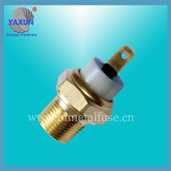
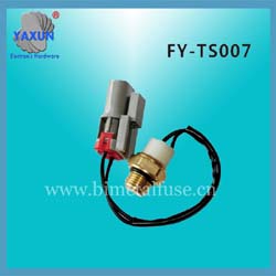
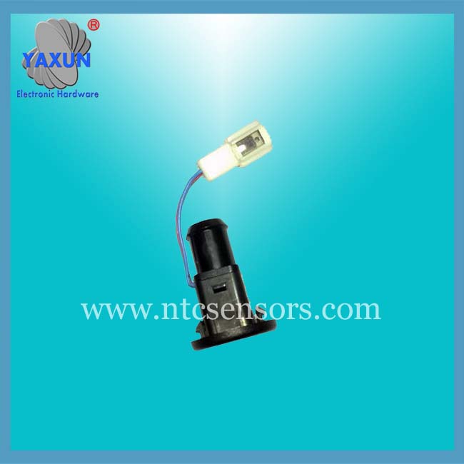
ECU / ECT Engine Coolant Temperature Sensor
- PRODUCT DETAIL
Resistance detection of cooling water temperature sensor
A. Check the ignition switch on the car, remove the cooling water temperature sensor wire connector, and use a digital high-impedance multimeter to test the resistance between the two terminals of the sensor. Its resistance value is inversely proportional to the temperature, and it should be less than 1KΩ in the heat engine.
B. Single piece inspection
Unplug the cooling water temperature sensor wire connector, and then remove the sensor from the engine; The sensor is placed in the water in the beaker, the water in the cup is heated, and the resistance value between the two terminals of the water temperature sensor under different water temperature conditions is measured with a multimeter file. Compare the measured value with the standard value. If it does not meet the standard, the water temperature sensor should be replaced.
(2) Detection of output signal voltage of cooling water temperature sensor
Install the cooling water temperature sensor, and plug the wire connector of this sensor. When the ignition switch is set to the "ON" position, the voltage signal is output from the test sensor between the water temperature sensor wire connector terminals
Failure phenomenon:
A Buick Excelle sedan, everything is normal when driving in urban areas, but the temperature of the coolant is too high when driving on the highway, the pointer of the coolant temperature meter points to the red area. Troubleshooting and troubleshooting:
After the test run, it was found that the engine cooling fan can work normally in low gear (two cooling fans are running at low speed at the same time), and the engine continues to accelerate to keep the engine warming up. When the cooling fan should run at high speed, the cooling fan on the left side stops running, and only the cooling fan on the right side runs at high speed. Check No. 6 and No. 21 fuses are normal; Use a multimeter to test the light blue wire on the left cooling fan motor, whose ground voltage is the battery voltage; At the moment when the cooling fan starts at low and high speed, you can hear the "click" sound when the relay is engaged. From the normal operation at low speed, you can determine that the two fan motors are normal. The control circuit of the vehicle's engine cooling fan is shown in Figure 2-7.
Its working principle is: When the coolant temperature sensor (ECT) senses that the cooling fan needs to run at low speed, the power system control module (PCM) controls its 6 grounds, the relay 12 works, and the moving contacts are attracted. Current through the movable contact 1 of relay 12 → terminal A2 → Left cooling fan motor one> Terminal A10 → Relay 9 dynamic break contact- → Terminal F12 → Right cooling fan motor + G117 grounding point, two cooling fan motors connected in series, each sharing half of the battery voltage, two cooling fan motors running at low speed.
When the coolant temperature sensor (ECT) senses that the cooling fan needs to run at high speed, the power system control module (PCM) controls its terminal 5 to ground, and relay 9 and relay 10 to ground at the same time. The relay 9's dynamic break contact is opened, the movable contact is closed, and the relay 10's movable contact is closed. At this time, the current is divided into two paths. All the way through No. 6 fuse → contact 12 of relay 12 → terminal A2 → left cooling fan motor 1> terminal A10 → Relay 9 moving contact → terminal C11 → G117 grounding point, the right cooling fan motor works under battery voltage (high speed); the other way is via fuse 21 → Terminal B6-> Terminal E10 → Relay 10 moving contact 1> Terminal F12- → Right cooling fan motor + G117 grounding point, right cooling fan motor works under battery voltage (high speed).
Based on the above analysis, it can be known that the dynamic break contact of the relay 9 is responsible for connecting the left and right fan motors in series at low speeds, and the high speed close contact connects the left fan motor to G117 ground at high speeds. The battery voltage is provided for the left fan motor, and the relay 10 is responsible for providing the battery voltage for the right cooling fan motor. If only relay 10 is activated and relay 9 is not activated, there will be a phenomenon in which both ends of the left cooling fan motor are connected to the battery voltage and cannot operate. At this time, only the right fan motor runs at high speed. Use a multimeter to test the grounding voltage of the gray wire on the left cooling fan motor, which is also the battery voltage. Remove the relay 9 and check, and find that the coil of the relay is open. After replacing a relay, test run and troubleshoot.
PREV:Different car series Engine Block Motor Temperature Sensor
NEXT:NONE
NEXT:NONE