Design of Signal Conditioning Circuit for Various Temperature Sensors
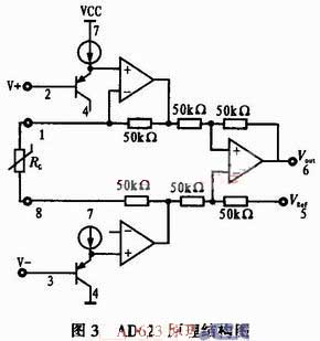
In Figure 2, R11 is a sampling resistor with a resistance of 10 kΩ and an accuracy of 1 ‰; The sensor product output current is 273.15μA at 0 °C, and the voltage across the resistor is 2.731 5 V; The sensor product output current is 373.15 μA at 100 °C, and the voltage across the resistor is 3.731 5 V; Since the sensor product output is not 0 when the temperature is 0 °C, the zero voltage should be subtracted before amplification. The voltage constant is shown in the figure VRef, which is obtained by dividing the 9V by the potentiometer RW11, and the size is 2.731 5 V; The op amp input differential voltage (Vin-VRef) is 0 V at 0 °C. In the figure U1 is the instrumentation amplifier. AD623 is selected, single-supply power supply, gain 1~1 000, its structure is shown in Figure 3. Simply adjust a resistor RG to change the gain, Vo = (1 + 100kΩ / RG) (V + ~ V-), the output signal reference level can be arbitrarily given within a certain range (using the 5-pin REF terminal).

The op amp input voltage Vin range is 2.731 5 to 3.731 5 V, minus 0 to 1 V after the reference (peak-to-peak 1 V), and the output voltage is required to be 1 to 5 V (peak-to-peak value 4 V) after amplification. Therefore, the amplifier has a magnification of four. Adjust the resistance RG between 1 and 8 (R12 and RW12 in Figure 2) to change the magnification; The op amp 5 pin inputs a voltage reference of 1 V, that is, the op amp input is 0 V (Vin ~ VRef) at 0 ° C, the output is 1 V (to ground), and 5 V is output at 100 ° C. The capacitor in Figure 2 is a decoupling capacitor or filter capacitor with a size of 0.1μF.
2.3 PT1000 Conditioning Circuit Heat
The PT1000 on the market has two-wire system, three-wire system and four-wire system according to the wiring form. The four-wire system has the highest accuracy, the two-wire system has the lowest, and the three-wire system is somewhere in between. In view of the accuracy requirements and the complexity of the connection, the three-wire system is adopted, and the three-wire system is adopted; This wiring method removes the inaccuracy of the zero point caused by the wire resistance.
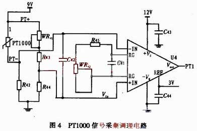
The three-wire PT1000 has one outlet at one end and two outlets at the other end. The connection is shown in Figure 4. In the figure, the blue line is connected to the power supply, the red line and the PT1000 form a bridge arm of the bridge, and the green line, WR41 and R43 form the other bridge arm; Wires of almost the same length (green line and red line) are introduced into both of the bridge arms. When the temperature changes, the two bridge arm lead resistances increase or decrease at the same time, and the bridge zero point is not affected, which improves the accuracy.
In Figure 4, WR41 is a zero potentiometer; The output of the bridge is directly connected to the AD623 op amp. he method of connecting and adjusting the gain is the same as in the previous section and will not be described here. When debugging, the PT1000 is realized by a resistor box, and the resistance value is obtained by the index table.

2.4 galvanic conditioning circuit
The basic principle of thermocouple temperature measurement is that two kinds of conductors with different compositions form a closed loop. When there is a temperature gradient at both ends, there will be current passing through the loop. At this time, there is an electromotive force between the two ends - the thermoelectromotive force. The higher temperature end is the working end, the lower temperature end is the cold end (free end), and the cold is usually at a constant temperature. If the temperature changes at the cold end when measuring, it will seriously affect the accuracy of the measurement. Therefore, certain measures are taken to compensate for the effect of the cold junction temperature change called the cold junction compensation of the thermocouple.

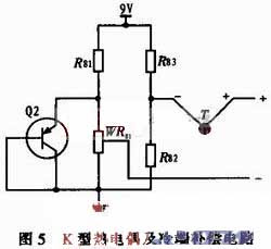
This design uses the transistor PN junction temperature characteristics for cold junction compensation, the cold junction compensation circuit and the thermocouple series, as shown in Figure 5. In the figure, T is a thermocouple, the other is a cold junction compensation circuit, the transistor uses a transistor 9012, and its voltage temperature change rate is about -2.1 mV/°C, and three resistors, a potentiometer, and a PNP triode form a bridge. When the temperature of the cold junction rises, the voltage drop of the PN junction decreases, the potential of the WR81 slider decreases, the intermediate potential of WR82 and R83 does not change, and the output of the bridge increases, which compensates for the temperature drift of the cold junction of the thermocouple. The opposite is true when the temperature is lowered. The output of the circuit is directly connected to the input of the op amp AD623.
3 Conclusion
The paper addresses several different types of temperature sensor products (ADS90, PT1000 and K-type thermocouples). The power circuit, the signal conversion circuit and the amplification and up-up circuit are designed to make the output of various sensor products reach a uniform standard signal of 1 to 5 V; The thermocouple, AD590 and PT1000 were simulated in the laboratory using high-precision voltage, current source and resistor box. The results show that the relative accuracy of the conditioning circuit can reach 0.1, and the uncertainty of 0.5% can be achieved after connecting the sensor; A weight of 55 g achieved the desired result.

The op amp input voltage Vin range is 2.731 5 to 3.731 5 V, minus 0 to 1 V after the reference (peak-to-peak 1 V), and the output voltage is required to be 1 to 5 V (peak-to-peak value 4 V) after amplification. Therefore, the amplifier has a magnification of four. Adjust the resistance RG between 1 and 8 (R12 and RW12 in Figure 2) to change the magnification; The op amp 5 pin inputs a voltage reference of 1 V, that is, the op amp input is 0 V (Vin ~ VRef) at 0 ° C, the output is 1 V (to ground), and 5 V is output at 100 ° C. The capacitor in Figure 2 is a decoupling capacitor or filter capacitor with a size of 0.1μF.
2.3 PT1000 Conditioning Circuit Heat
The PT1000 on the market has two-wire system, three-wire system and four-wire system according to the wiring form. The four-wire system has the highest accuracy, the two-wire system has the lowest, and the three-wire system is somewhere in between. In view of the accuracy requirements and the complexity of the connection, the three-wire system is adopted, and the three-wire system is adopted; This wiring method removes the inaccuracy of the zero point caused by the wire resistance.
The three-wire PT1000 has one outlet at one end and two outlets at the other end. The connection is shown in Figure 4. In the figure, the blue line is connected to the power supply, the red line and the PT1000 form a bridge arm of the bridge, and the green line, WR41 and R43 form the other bridge arm; Wires of almost the same length (green line and red line) are introduced into both of the bridge arms. When the temperature changes, the two bridge arm lead resistances increase or decrease at the same time, and the bridge zero point is not affected, which improves the accuracy.
In Figure 4, WR41 is a zero potentiometer; The output of the bridge is directly connected to the AD623 op amp. he method of connecting and adjusting the gain is the same as in the previous section and will not be described here. When debugging, the PT1000 is realized by a resistor box, and the resistance value is obtained by the index table.

2.4 galvanic conditioning circuit
The basic principle of thermocouple temperature measurement is that two kinds of conductors with different compositions form a closed loop. When there is a temperature gradient at both ends, there will be current passing through the loop. At this time, there is an electromotive force between the two ends - the thermoelectromotive force. The higher temperature end is the working end, the lower temperature end is the cold end (free end), and the cold is usually at a constant temperature. If the temperature changes at the cold end when measuring, it will seriously affect the accuracy of the measurement. Therefore, certain measures are taken to compensate for the effect of the cold junction temperature change called the cold junction compensation of the thermocouple.

This design uses the transistor PN junction temperature characteristics for cold junction compensation, the cold junction compensation circuit and the thermocouple series, as shown in Figure 5. In the figure, T is a thermocouple, the other is a cold junction compensation circuit, the transistor uses a transistor 9012, and its voltage temperature change rate is about -2.1 mV/°C, and three resistors, a potentiometer, and a PNP triode form a bridge. When the temperature of the cold junction rises, the voltage drop of the PN junction decreases, the potential of the WR81 slider decreases, the intermediate potential of WR82 and R83 does not change, and the output of the bridge increases, which compensates for the temperature drift of the cold junction of the thermocouple. The opposite is true when the temperature is lowered. The output of the circuit is directly connected to the input of the op amp AD623.
3 Conclusion
The paper addresses several different types of temperature sensor products (ADS90, PT1000 and K-type thermocouples). The power circuit, the signal conversion circuit and the amplification and up-up circuit are designed to make the output of various sensor products reach a uniform standard signal of 1 to 5 V; The thermocouple, AD590 and PT1000 were simulated in the laboratory using high-precision voltage, current source and resistor box. The results show that the relative accuracy of the conditioning circuit can reach 0.1, and the uncertainty of 0.5% can be achieved after connecting the sensor; A weight of 55 g achieved the desired result.


