Design and Commissioning of Temperature sensor Temperature Control Circuit
I. Experimental purpose:
1. Learn how to use a variety of unit components to form a temperature control circuit.
2. Master the installation and commissioning of the temperature control circuit.
II. Experimental requirements: design with integrated operational amplifier
Keywords: temperature control
Design and commissioning of temperature control circuit
I. Experimental purpose:
1. Learn how to use a variety of unit components to form a temperature control circuit.
2. Master the installation and commissioning of the temperature control circuit.
II. Experimental requirements:
Design a temperature control circuit with integrated operational amplifier, temperature control 0~100 degrees adjustable, temperature control accuracy ± 3 °C
III. Design tips:
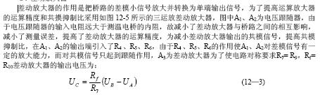
The overall design of the temperature control circuit is shown in Figure 12-1. The function of the sensor is to convert the temperature change into a quantity of electricity to change the output voltage of the temperature measuring bridge. The output voltage of the temperature measuring bridge is amplified by a differential amplifier and applied to the voltage comparator to control the output of the voltage comparator, and then the high and low level control output circuit of the voltage comparator outputs or stops the heating.
Temperature sensor ---- temperature measuring bridge ---- differential amplifier ---- voltage comparator ---- voltage comparator ---- execution circuit
1. The temperature sensor
Temperature sensitive components are called temperature sensors. There are many types of temperature sensors, and there are thermal resistors made of a metal material (platinum, copper, and nickel). Useful semiconductor materials to make hungry thermistors and thermocouples and so on. The thermistor has a large temperature coefficient and high sensitivity, and can detect changes in temperature. Therefore, the thermistor is used in this experiment.
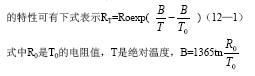
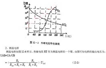
The thermistor has a negative temperature coefficient thermistor (temperature rise, resistance reduction) NTC and positive temperature coefficient thermistor PTC. The characteristic curves of NTC and PTC are shown in Figure 12-2. It can be seen from the figure that both NTC and PTC are exponential curves. The PN junction of NTC transistor is made of semiconductor material, so it can also be used as temperature sensing element. For example, if the emission of 3DG6 is positive, the relationship between the voltage drop of the emission junction and temperature will be as shown in Figure 12-3. It can be seen from the figure that in the range of 0-100 'C, the forward voltage drop of the emitter junction is linear with temperature. For every 1 °C increase in temperature, the forward voltage drop of the PN junction changes by -2 mv/°C.
During the temperature measurement and temperature control process, when the temperature changes, the resistance value of the RT changes, causing the bridge output voltage to change. Rw1 is the temperature setting potentiometer. Adjusting the resistance of Rw1 can change the temperature control point.
2, differential amplifier
4, voltage comparator and control circuit
The voltage comparator uses a hysteresis comparator as shown in Figure 12-6. The threshold voltage of the hysteresis comparator is:
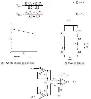
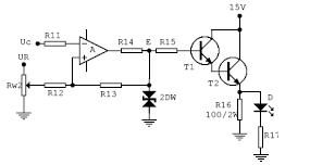
Figure 12-6 Comparator and control circuit diagram
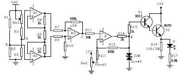
Figure 12-7 Temperature control circuit design
The control process of the temperature control circuit is:
When the circuit is just turned on, │UA-UB│ is small, VC<UTH1, and point E is high level U2, and T1 and T2 are saturated. The 15V power supply heats 100Ω/2W to increase the heater temperature, and Rr gradually decreases as the temperature increases. UA-UB gradually increases, and UC increases. When UC=UTH1, point E jumps from high level to low level -Uz, T1 and T2 are cut off, the heater stops heating, and the temperature decreases. The increase in the resistance of RT reduces │UA-UB│. When it is reduced to UC=UTH2, the E point is flipped from low level to high level and heated again. If the cycle is repeated, the temperature is made constant.
Requirement: Calculate other parameters of the circuit based on the given component parameters and voltages in the circuit.
V. Installation and commissioning of temperature control circuit
1. First connect the designed temperature control circuit on the experiment board, and then solder it to the printed board after successful debugging.
2. Ground the point B in Figure 12-7, input the DC voltage of -30MV from point A, measure UC, and calculate the magnification of the three-into-differential magnifier.
3. Point B is grounded. Enter a -0.5 - +0.5 continuously adjustable DC voltage from point A. Observe the jump of the E point at the output of the comparator with an oscilloscope, measure and record the input voltage UC when the positive and negative transitions occur at the E point, and draw the hysteresis characteristic curve.
4. Control temperature calibration:
Set the temperature control range to TL-TH. When the temperature control range is calibrated, the RT is placed in the thermostat and is connected to the mercury body of the standard thermometer.
1. Learn how to use a variety of unit components to form a temperature control circuit.
2. Master the installation and commissioning of the temperature control circuit.
II. Experimental requirements: design with integrated operational amplifier
Keywords: temperature control
Design and commissioning of temperature control circuit
I. Experimental purpose:
1. Learn how to use a variety of unit components to form a temperature control circuit.
2. Master the installation and commissioning of the temperature control circuit.
II. Experimental requirements:
Design a temperature control circuit with integrated operational amplifier, temperature control 0~100 degrees adjustable, temperature control accuracy ± 3 °C
III. Design tips:
The overall design of the temperature control circuit is shown in Figure 12-1. The function of the sensor is to convert the temperature change into a quantity of electricity to change the output voltage of the temperature measuring bridge. The output voltage of the temperature measuring bridge is amplified by a differential amplifier and applied to the voltage comparator to control the output of the voltage comparator, and then the high and low level control output circuit of the voltage comparator outputs or stops the heating.
Temperature sensor ---- temperature measuring bridge ---- differential amplifier ---- voltage comparator ---- voltage comparator ---- execution circuit
1. The temperature sensor
Temperature sensitive components are called temperature sensors. There are many types of temperature sensors, and there are thermal resistors made of a metal material (platinum, copper, and nickel). Useful semiconductor materials to make hungry thermistors and thermocouples and so on. The thermistor has a large temperature coefficient and high sensitivity, and can detect changes in temperature. Therefore, the thermistor is used in this experiment.
The thermistor has a negative temperature coefficient thermistor (temperature rise, resistance reduction) NTC and positive temperature coefficient thermistor PTC. The characteristic curves of NTC and PTC are shown in Figure 12-2. It can be seen from the figure that both NTC and PTC are exponential curves. The PN junction of NTC transistor is made of semiconductor material, so it can also be used as temperature sensing element. For example, if the emission of 3DG6 is positive, the relationship between the voltage drop of the emission junction and temperature will be as shown in Figure 12-3. It can be seen from the figure that in the range of 0-100 'C, the forward voltage drop of the emitter junction is linear with temperature. For every 1 °C increase in temperature, the forward voltage drop of the PN junction changes by -2 mv/°C.
During the temperature measurement and temperature control process, when the temperature changes, the resistance value of the RT changes, causing the bridge output voltage to change. Rw1 is the temperature setting potentiometer. Adjusting the resistance of Rw1 can change the temperature control point.
2, differential amplifier
4, voltage comparator and control circuit
The voltage comparator uses a hysteresis comparator as shown in Figure 12-6. The threshold voltage of the hysteresis comparator is:
Figure 12-6 Comparator and control circuit diagram
Changing the reference voltage UR of the hysteresis comparator can change the temperature control range, which is determined by the hysteresis bandwidth UTH1 - UH2 of the comparator. UTH1 and UTH2 can be calculated from the temperature control accuracy required by the design, and the other two values are calculated by the formulas 12-4, 12-5 according to any two of U2, UR, U12, and U13 given by the circuit.
Generally, the heater is controlled by a relay controlled by a switching circuit or a thyristor. Here, it is controlled by a composite pipe composed of T1 and T2. The heater is simulated by a 100/2W resistor. In the experiment, the 100Ω/2W resistor is placed close to the thermistor RT, and the LED D is used for heating.
display.
IV. Reference circuit:
Combine the unit circuits in the design hints to facilitate the operation of the temperature control circuit shown in Figure 12-7.
Figure 12-7 Temperature control circuit design
The control process of the temperature control circuit is:
When the circuit is just turned on, │UA-UB│ is small, VC<UTH1, and point E is high level U2, and T1 and T2 are saturated. The 15V power supply heats 100Ω/2W to increase the heater temperature, and Rr gradually decreases as the temperature increases. UA-UB gradually increases, and UC increases. When UC=UTH1, point E jumps from high level to low level -Uz, T1 and T2 are cut off, the heater stops heating, and the temperature decreases. The increase in the resistance of RT reduces │UA-UB│. When it is reduced to UC=UTH2, the E point is flipped from low level to high level and heated again. If the cycle is repeated, the temperature is made constant.
Requirement: Calculate other parameters of the circuit based on the given component parameters and voltages in the circuit.
V. Installation and commissioning of temperature control circuit
1. First connect the designed temperature control circuit on the experiment board, and then solder it to the printed board after successful debugging.
2. Ground the point B in Figure 12-7, input the DC voltage of -30MV from point A, measure UC, and calculate the magnification of the three-into-differential magnifier.
3. Point B is grounded. Enter a -0.5 - +0.5 continuously adjustable DC voltage from point A. Observe the jump of the E point at the output of the comparator with an oscilloscope, measure and record the input voltage UC when the positive and negative transitions occur at the E point, and draw the hysteresis characteristic curve.
4. Control temperature calibration:
Set the temperature control range to TL-TH. When the temperature control range is calibrated, the RT is placed in the thermostat and is connected to the mercury body of the standard thermometer.


