Cold Junction Compensation Method for Temperature Measuring Instrument Based on Thermocouple
Thermocouple is a kind of commonly used temperature sensor. It uses thermoelectric effect to measure temperature according to thermoelectric electromotive force produced by temperature difference between hot and cold ends. It has the advantages of high measurement accuracy, simple structure and convenient use. It has been widely used in temperature measuring instruments. The general cold junction compensation method has a large influence on the measurement result due to its complicated structure, large noise, and poor linearity.
1 Universal thermocouple cold junction compensation method
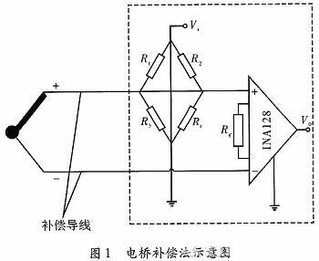
1.1 Principle of Bridge Compensation Method
As shown in Figure 1, where R1, R2, R3 have the same resistance. Made of manganese copper with a temperature coefficient of approximately zero, ie its resistance does not change with temperature. Rt uses the thermal resistance PT1000, which is in the same temperature field as the cold junction of the thermocouple, and its resistance value changes with temperature. When the temperature rises, the resistance increases. When the cold junction temperature is zero, R1=R3=R2=R1, which makes the output of the bridge zero. If the temperature of the cold junction rises, the thermoelectric potential of the thermocouple will decrease and the measurement error will be caused. But at this time, the resistance of PT1000 will increase with the increase of temperature, then the compensation bridge will be out of balance and the output value will not be zero. The change value of bridge output is the same as that of thermocouple thermoelectric potential, and the change direction of the two is opposite. The two cancel each other so that the total output does not change with the change of cold end temperature.
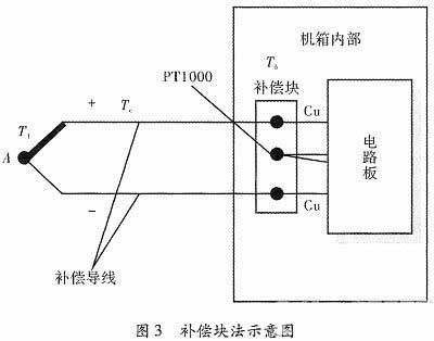
1.2 Experimental data record
The thermoelectric potential of the K-type thermocouple was simulated with a millivolt voltage generator during the experiment. After the A/D conversion is completed on the circuit board, the upper computer is uploaded through the MCU, and the A/D value is converted into temperature by the host computer and displayed. The experimental results are shown in Table 1.
This method requires high precision for R1, R2, and R3, and V+ noise, temperature drift is small, and stability is high. In order to meet the experimental requirements, it is necessary to make the bridge current a suitable value, and the debugging is difficult.
When performing multi-channel measurement, multiple devices need to be arranged, and the structure is complicated.
2 New method for thermocouple cold junction compensation
2.1 Principle
This method measures the cold junction temperature from the PT1000. After A/D conversion, the resistance value is transferred from MCU to PC, which is converted into voltage value by software and added to the voltage of thermocouple. Then, the influence of temperature change at cold end is eliminated by compensation block, so as to compensate.
2.2 Design of compensation block
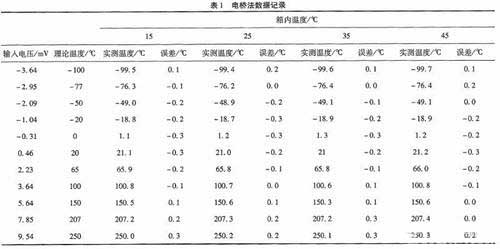
The main device for cold-end compensation of this method is a piece of aluminum with good thermal conductivity, and its structure is shown in Fig. 2.
 Three through holes are drilled on the transverse central axis of the cuboid aluminium block, and cut along the transverse central axis. In the subsequent wiring process, the two compensation wires are pressed as two left and right through holes, and the middle through holes are pressed into the thermal resistance PT1000. In order to ensure the uniformity of heat conduction during the press-in process, the diameters of the thermal resistance and the compensation wire should be consistent and fully in contact with the compensation block, and the insulation material should be the same.
2.3 Compensation circuit design
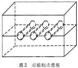
As shown in Figure 3, the thermocouple is connected to the compensation board in the instrument box through the compensation wire and then connected to the circuit board inside the box through the Cu wire.
The compensation block and the cold junction of the thermocouple are in the instrument box.
The PT1000 is used to measure the temperature inside the instrument box. Toc is the ambient temperature outside the instrument box.
Due to the requirements of program design, when the compensation circuit is not connected, the upper computer shows that the temperature T1 is the actual temperature Tr at A plus the temperature Tb in the box, that is, T1 = Tr + Tb. In the actual use of the instrument, the temperature inside the temperature box will change. To avoid the influence of the temperature change inside the box on the actual measured temperature, the access compensation circuit is designed.
When the temperature inside the instrument box rises, the upper computer will display the temperature T1 as the temperature inside the box rises. After the compensation circuit is added, the compensation block is evenly heated in the box, and both ends of the compensation wire are in the same temperature field as the PT1000. The voltage generated by the compensation wire can offset the influence of the temperature change at the cold end, ensuring that the measured value is not affected by the temperature change inside the box, and is only related to the ambient temperature Tc outside the box, that is, T1=Tr+Tc.
2.4 Experimental data record
The experimental process is similar to that of bridge method. A millivolt voltage generator is used to simulate the thermoelectric potential of K-type thermocouple. After the A/D conversion is completed on the circuit board, the upper computer is uploaded through the MCU, and the A/D value is converted into temperature by the host computer and displayed. The experimental results are shown in Table 2.
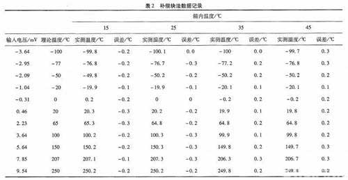 As can be seen from the above table, the compensation method has higher accuracy, the error is within 1 ° C and the linearity is good. In the multi-channel measurement, only a few sets of through holes can be added to the compensation block, and the structure is simple to meet the needs of industrial applications.
3 Comparison and analysis of data between compensation block method and bridge method
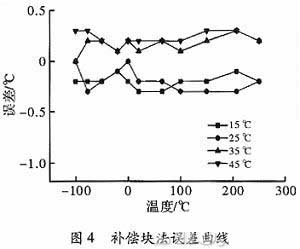
According to the data in Table 1 and Table 2, the error curves of the two methods at different temperatures are respectively made with the input voltage as the abscissa and the error value as the ordinate, as shown in Fig. 4 and Fig. 5.
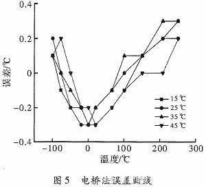
As can be seen from the graph in Fig. 5, the linearity of the bridge method is poor. Because the input and output characteristics of the thermocouple and the output characteristics of the compensating bridge are both non-linear and do not coincide, the compensation error can be completely compensated within the compensation range only at the cold end temperature corresponding to the intersection point of the two curves. Other cold junction temperatures can only be partially compensated, and there is a compensation error. In actual use, more complex circuits are needed to reduce the error due to nonlinearity.
It can be seen from the four curves of the compensation block method of Fig. 4 that the maximum error does not exceed 1 °C and the linearity is better, which can more accurately meet the measurement requirements.
4 Conclusion
The cold junction compensation method based on thermocouple based on thermocouple is simple, stable, low noise and good linearity. When performing multi-channel measurement, it only needs to punch a few through holes on the compensation block to press the compensation wire into it, and the accuracy of the measurement is ensured under the premise of controlling the cost, and the technical index is reached.
1 Universal thermocouple cold junction compensation method
1.1 Principle of Bridge Compensation Method
As shown in Figure 1, where R1, R2, R3 have the same resistance. Made of manganese copper with a temperature coefficient of approximately zero, ie its resistance does not change with temperature. Rt uses the thermal resistance PT1000, which is in the same temperature field as the cold junction of the thermocouple, and its resistance value changes with temperature. When the temperature rises, the resistance increases. When the cold junction temperature is zero, R1=R3=R2=R1, which makes the output of the bridge zero. If the temperature of the cold junction rises, the thermoelectric potential of the thermocouple will decrease and the measurement error will be caused. But at this time, the resistance of PT1000 will increase with the increase of temperature, then the compensation bridge will be out of balance and the output value will not be zero. The change value of bridge output is the same as that of thermocouple thermoelectric potential, and the change direction of the two is opposite. The two cancel each other so that the total output does not change with the change of cold end temperature.
1.2 Experimental data record
The thermoelectric potential of the K-type thermocouple was simulated with a millivolt voltage generator during the experiment. After the A/D conversion is completed on the circuit board, the upper computer is uploaded through the MCU, and the A/D value is converted into temperature by the host computer and displayed. The experimental results are shown in Table 1.
This method requires high precision for R1, R2, and R3, and V+ noise, temperature drift is small, and stability is high. In order to meet the experimental requirements, it is necessary to make the bridge current a suitable value, and the debugging is difficult.
When performing multi-channel measurement, multiple devices need to be arranged, and the structure is complicated.
2 New method for thermocouple cold junction compensation
2.1 Principle
This method measures the cold junction temperature from the PT1000. After A/D conversion, the resistance value is transferred from MCU to PC, which is converted into voltage value by software and added to the voltage of thermocouple. Then, the influence of temperature change at cold end is eliminated by compensation block, so as to compensate.
2.2 Design of compensation block
The main device for cold-end compensation of this method is a piece of aluminum with good thermal conductivity, and its structure is shown in Fig. 2.
2.3 Compensation circuit design
As shown in Figure 3, the thermocouple is connected to the compensation board in the instrument box through the compensation wire and then connected to the circuit board inside the box through the Cu wire.
The compensation block and the cold junction of the thermocouple are in the instrument box.
The PT1000 is used to measure the temperature inside the instrument box. Toc is the ambient temperature outside the instrument box.
Due to the requirements of program design, when the compensation circuit is not connected, the upper computer shows that the temperature T1 is the actual temperature Tr at A plus the temperature Tb in the box, that is, T1 = Tr + Tb. In the actual use of the instrument, the temperature inside the temperature box will change. To avoid the influence of the temperature change inside the box on the actual measured temperature, the access compensation circuit is designed.
When the temperature inside the instrument box rises, the upper computer will display the temperature T1 as the temperature inside the box rises. After the compensation circuit is added, the compensation block is evenly heated in the box, and both ends of the compensation wire are in the same temperature field as the PT1000. The voltage generated by the compensation wire can offset the influence of the temperature change at the cold end, ensuring that the measured value is not affected by the temperature change inside the box, and is only related to the ambient temperature Tc outside the box, that is, T1=Tr+Tc.
2.4 Experimental data record
The experimental process is similar to that of bridge method. A millivolt voltage generator is used to simulate the thermoelectric potential of K-type thermocouple. After the A/D conversion is completed on the circuit board, the upper computer is uploaded through the MCU, and the A/D value is converted into temperature by the host computer and displayed. The experimental results are shown in Table 2.
3 Comparison and analysis of data between compensation block method and bridge method
According to the data in Table 1 and Table 2, the error curves of the two methods at different temperatures are respectively made with the input voltage as the abscissa and the error value as the ordinate, as shown in Fig. 4 and Fig. 5.
As can be seen from the graph in Fig. 5, the linearity of the bridge method is poor. Because the input and output characteristics of the thermocouple and the output characteristics of the compensating bridge are both non-linear and do not coincide, the compensation error can be completely compensated within the compensation range only at the cold end temperature corresponding to the intersection point of the two curves. Other cold junction temperatures can only be partially compensated, and there is a compensation error. In actual use, more complex circuits are needed to reduce the error due to nonlinearity.
It can be seen from the four curves of the compensation block method of Fig. 4 that the maximum error does not exceed 1 °C and the linearity is better, which can more accurately meet the measurement requirements.
4 Conclusion
The cold junction compensation method based on thermocouple based on thermocouple is simple, stable, low noise and good linearity. When performing multi-channel measurement, it only needs to punch a few through holes on the compensation block to press the compensation wire into it, and the accuracy of the measurement is ensured under the premise of controlling the cost, and the technical index is reached.


