Ceramic Electric Heating Element Control System
The electric heating system has gone through the long process of ordinary heating wire, alloy heating wire, electric heating film, PTC heating element, and the alumina ceramic heating core (MCH) widely used today. The so-called MCH alumina ceramic heating sheet is based on high thermal conductivity ceramic - alumina ceramic. A heat generating circuit is formed by directly printing a heat resistant refractory alloy on an alumina body as an internal electrode. After vacuum pressing, two sheets of alumina green sheets are co-fired at a high temperature of about 1600 ° C, and finally, brazed leads are taken out. Compared with traditional electric heating elements, it has the advantages of stable performance, long mission, high efficiency, energy saving, uniform surface temperature and good insulation performance. The thermal response time is short, the thermal inertia is small, the heating rate is fast, and the heating temperature is up to 700 °C. No visible light radiation, good surface divergence rate, safe and environmentally friendly, in line with EU (ROHS and WEEE) environmental requirements. Therefore, it has completely replaced the application of various heating wires and PTC heating elements in new small appliances and beauty care products.
 Now common product specifications are sheet thickness of 1.2mm, as shown in Figure 1 and Figure 2, length and width specifications are 70 × 7, 70 × 10, 70 × 15, 70 × 20, 70 × 30 and so on. Normal temperature resistance is usually 40/60/80/120/150 (Ω). Depending on the manufacturer, there are different specifications, the working temperature is 100-300 °C, and the maximum working temperature is greater than 500 °C. It can reach 200 °C in 7-10 seconds for direct heating of 110/220V, and reaches the highest temperature in about 20 seconds. However, when used in beauty care products such as hair curlers and hair straighteners (ion hot), it is generally required to have a stable temperature in the range of 100 ° C -250 ° C steplessly adjustable or sub-range temperature adjustment. In addition, high temperature stability is required, so a corresponding temperature control system is generally required.
The initial temperature control system generally uses NTC to measure the temperature on the heating element, and then the MCU or a dedicated ASIC detects the resistance of the NTC and controls the thyristor output. These circuits are complex in structure and high in cost (NTC + MCU), so they are quickly eliminated. At present, the more advanced solution is to use the characteristic that the resistance of the internal heating element of the MCH heating head changes with temperature, and directly measure the resistance value of the heating element to measure the temperature, thereby directly controlling the stable temperature. This feature approximates the PTC characteristics, but the Curie points of the components are different. For example, a 33Ω heater with a normal temperature resistance rises to about 47Ω at 120°C, and rises to about 61Ω when the temperature reaches 250°C. A more typical separation element scheme is CD4017 + LM358 or even a single piece of LM358, LM2903, etc. A typical control circuit is shown in Figure 3:

R14A/B step-down D2D3 regulator is filtered by D4C3 and then output DC voltage of about 24V for later use. Q4/Q5 and its auxiliary circuits form an AC zero-crossing detection circuit for driving Q3. A pulse of about 100 uS is output every time the alternating current crosses zero, and the control Q2 supplies a pulsed power supply of about 100 uS to the main control circuit composed of the LM2903. The positive input of U1A is matched with two resistor chains for adjusting the set temperature point, where SVR1 sets the maximum temperature and SVR2 sets the lowest temperature (or vice versa). VR1 allows the positive input voltage of U1A to be steplessly adjustable between the two limits, thereby linearly adjusting the set temperature. Because the heating head and R15/R14 are connected in series by D7, when the temperature of the heating head rises and the resistance rises, the voltage taken out through the positive end of D7 rises, and the voltage is input to the two inverting inputs of the IC by D8. It is judged by U1A whether the voltage rises above the set point of VR1. Therefore, the output terminal controls whether the D5/R8/C4 loop provides a comparison pulse to the positive pole of U1B for driving the U1B comparator to control the conduction of the SCR1 unidirectional thyristor to achieve stable temperature.
The circuit has lower cost, but the structure is more complicated, and the various parts of the circuit affect each other, and the temperature control effect is general, especially when the temperature control circuit fails. For example, when any adjustable resistor is open circuit, the output of the circuit will keep the SCR continuously turned on, and the temperature of the heating head will rise sharply, and may even exceed 500 ° C, thus burning the heating head and even dangerous. Last year, there were several cases in which hair was complained and claimed because of a hair straightener. Therefore, manufacturers need newer, simpler, and more secure control systems.
The PT8A330x is a series of newly designed domestic integrated circuits that completely improve the drawbacks of the above circuits. The IC uses a pulse mode to trigger the thyristor, which has strong triggering capability, low power consumption, and a very simple peripheral circuit, especially its output driver pin-pin 8-Gate. A number of special measures have been taken inside the IC to ensure that the pin is reliably pulled low when the IC is inactive or fails, and the thyristor is turned off so that it does not cause a safety problem. A typical application circuit is shown in Figure 4. This circuit can operate directly in the voltage range of 110V - 240V. The half-wave rectifying resistor step-down circuit composed of D2/R1/C1 /C2 supplies about 5V to the IC and the auxiliary circuit, and LED1/LED2 is used to indicate the working state. The AC zero-crossing detection circuit is composed of R3/R4, which is used to provide a zero-crossing trigger signal to the IC, and is used to detect whether the circuit is powered by 110V or 220V, so that the IC can switch between different heating control rates. For example, for a heating head with a small resistance value, when the power is turned on in a 110V environment, the full fire number is used for heating. When using 220V, 3/8 or 1/4 fire number heating is used to protect the heating head and the system from damage due to too fast heating.
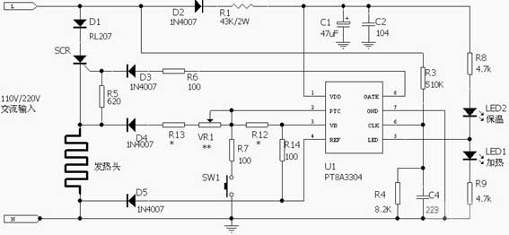
The principle of the IC temperature measurement is as follows: VR1 is used to adjust the set temperature. The left side of the heating head resistor +R13+VR1 forms one arm of the Wheatstone bridge. The right half of VR1 and R12 form the other arm. The balance detection of this path is input to the internal comparator end by pin 2. The IC provides two additional arms inside and inputs the other end of the comparator inside. During temperature measurement (controlled by the IC to measure temperature during heating stop). The VB pin outputs a voltage close to VCC to the bridge, and the internal high-precision comparator detects the balance of the bridge to determine the temperature and its error margin. After the internal approximate PID operation, the control pin 8 outputs a pulse trigger signal (zero-crossing trigger) to control the conduction of the thyristor, thereby accurately controlling the temperature of the system. When the power is turned on or OFF, the whole system is in the standby state, and the on/off system heating function is controlled by the tact switch SW1.
The feature of this scheme is that the IC uses an approximate PID control algorithm instead of the ON/OFF control as a general system. It is well known that in engineering practice, the most widely used regulator control law is proportional, integral, differential control, referred to as PID control, also known as PID adjustment. Simply put, for the temperature control system, the ON/OFF control turns on the heating head heating when it detects that the temperature drops to the set lower limit, and stops the heating after the temperature rises to the set upper limit. Therefore, its temperature always swings up and down around the set point. The output of the PID controller is not only proportional to the temperature offset (input error signal) (proportional control). It is also proportional to the rate of change (differential) of the temperature offset and the time accumulation (integration) of the temperature offset. Thus, since the system has the proportional + derivative control, the error suppression operation can be started in advance, so that the heat generating head having a large thermal inertia or hysteresis is used. The proportional + derivative (PD) controller can significantly improve the dynamic characteristics of the system during the adjustment process; The integral term refers to the integral of the temperature drift over time, and the integral term increases as time increases. Thus, even if the error is small, the integral term increases with time, which pushes the output of the heater head to increase and further reduces the steady-state error until it equals zero. Therefore, using a proportional + integral (PI) controller allows the system to have no steady-state error after entering steady state.
For PID adjustment, the proportional relationship and the setting of the integral differential value are very critical. The PT8A330x integrated designer has many years of research experience on ceramic heating elements, and has set several different sets of highly targeted PID parameters in the IC. Thus, a series of models such as PT8A3300-3307 have been produced, and each model is divided into different categories such as H/L, which are respectively used for ceramic heating heads of various performances. After adopting the above measures, the temperature control curve of this series of ICs has been perfect. Whether it is temperature stability, heating rate or temperature after cooling, it has a fairly obvious leading edge in the industry. It is believed that it will definitely promote the overall technical level of electric heating personal care appliances and small household appliances.
The initial temperature control system generally uses NTC to measure the temperature on the heating element, and then the MCU or a dedicated ASIC detects the resistance of the NTC and controls the thyristor output. These circuits are complex in structure and high in cost (NTC + MCU), so they are quickly eliminated. At present, the more advanced solution is to use the characteristic that the resistance of the internal heating element of the MCH heating head changes with temperature, and directly measure the resistance value of the heating element to measure the temperature, thereby directly controlling the stable temperature. This feature approximates the PTC characteristics, but the Curie points of the components are different. For example, a 33Ω heater with a normal temperature resistance rises to about 47Ω at 120°C, and rises to about 61Ω when the temperature reaches 250°C. A more typical separation element scheme is CD4017 + LM358 or even a single piece of LM358, LM2903, etc. A typical control circuit is shown in Figure 3:
R14A/B step-down D2D3 regulator is filtered by D4C3 and then output DC voltage of about 24V for later use. Q4/Q5 and its auxiliary circuits form an AC zero-crossing detection circuit for driving Q3. A pulse of about 100 uS is output every time the alternating current crosses zero, and the control Q2 supplies a pulsed power supply of about 100 uS to the main control circuit composed of the LM2903. The positive input of U1A is matched with two resistor chains for adjusting the set temperature point, where SVR1 sets the maximum temperature and SVR2 sets the lowest temperature (or vice versa). VR1 allows the positive input voltage of U1A to be steplessly adjustable between the two limits, thereby linearly adjusting the set temperature. Because the heating head and R15/R14 are connected in series by D7, when the temperature of the heating head rises and the resistance rises, the voltage taken out through the positive end of D7 rises, and the voltage is input to the two inverting inputs of the IC by D8. It is judged by U1A whether the voltage rises above the set point of VR1. Therefore, the output terminal controls whether the D5/R8/C4 loop provides a comparison pulse to the positive pole of U1B for driving the U1B comparator to control the conduction of the SCR1 unidirectional thyristor to achieve stable temperature.
The circuit has lower cost, but the structure is more complicated, and the various parts of the circuit affect each other, and the temperature control effect is general, especially when the temperature control circuit fails. For example, when any adjustable resistor is open circuit, the output of the circuit will keep the SCR continuously turned on, and the temperature of the heating head will rise sharply, and may even exceed 500 ° C, thus burning the heating head and even dangerous. Last year, there were several cases in which hair was complained and claimed because of a hair straightener. Therefore, manufacturers need newer, simpler, and more secure control systems.
The PT8A330x is a series of newly designed domestic integrated circuits that completely improve the drawbacks of the above circuits. The IC uses a pulse mode to trigger the thyristor, which has strong triggering capability, low power consumption, and a very simple peripheral circuit, especially its output driver pin-pin 8-Gate. A number of special measures have been taken inside the IC to ensure that the pin is reliably pulled low when the IC is inactive or fails, and the thyristor is turned off so that it does not cause a safety problem. A typical application circuit is shown in Figure 4. This circuit can operate directly in the voltage range of 110V - 240V. The half-wave rectifying resistor step-down circuit composed of D2/R1/C1 /C2 supplies about 5V to the IC and the auxiliary circuit, and LED1/LED2 is used to indicate the working state. The AC zero-crossing detection circuit is composed of R3/R4, which is used to provide a zero-crossing trigger signal to the IC, and is used to detect whether the circuit is powered by 110V or 220V, so that the IC can switch between different heating control rates. For example, for a heating head with a small resistance value, when the power is turned on in a 110V environment, the full fire number is used for heating. When using 220V, 3/8 or 1/4 fire number heating is used to protect the heating head and the system from damage due to too fast heating.
The principle of the IC temperature measurement is as follows: VR1 is used to adjust the set temperature. The left side of the heating head resistor +R13+VR1 forms one arm of the Wheatstone bridge. The right half of VR1 and R12 form the other arm. The balance detection of this path is input to the internal comparator end by pin 2. The IC provides two additional arms inside and inputs the other end of the comparator inside. During temperature measurement (controlled by the IC to measure temperature during heating stop). The VB pin outputs a voltage close to VCC to the bridge, and the internal high-precision comparator detects the balance of the bridge to determine the temperature and its error margin. After the internal approximate PID operation, the control pin 8 outputs a pulse trigger signal (zero-crossing trigger) to control the conduction of the thyristor, thereby accurately controlling the temperature of the system. When the power is turned on or OFF, the whole system is in the standby state, and the on/off system heating function is controlled by the tact switch SW1.
The feature of this scheme is that the IC uses an approximate PID control algorithm instead of the ON/OFF control as a general system. It is well known that in engineering practice, the most widely used regulator control law is proportional, integral, differential control, referred to as PID control, also known as PID adjustment. Simply put, for the temperature control system, the ON/OFF control turns on the heating head heating when it detects that the temperature drops to the set lower limit, and stops the heating after the temperature rises to the set upper limit. Therefore, its temperature always swings up and down around the set point. The output of the PID controller is not only proportional to the temperature offset (input error signal) (proportional control). It is also proportional to the rate of change (differential) of the temperature offset and the time accumulation (integration) of the temperature offset. Thus, since the system has the proportional + derivative control, the error suppression operation can be started in advance, so that the heat generating head having a large thermal inertia or hysteresis is used. The proportional + derivative (PD) controller can significantly improve the dynamic characteristics of the system during the adjustment process; The integral term refers to the integral of the temperature drift over time, and the integral term increases as time increases. Thus, even if the error is small, the integral term increases with time, which pushes the output of the heater head to increase and further reduces the steady-state error until it equals zero. Therefore, using a proportional + integral (PI) controller allows the system to have no steady-state error after entering steady state.
For PID adjustment, the proportional relationship and the setting of the integral differential value are very critical. The PT8A330x integrated designer has many years of research experience on ceramic heating elements, and has set several different sets of highly targeted PID parameters in the IC. Thus, a series of models such as PT8A3300-3307 have been produced, and each model is divided into different categories such as H/L, which are respectively used for ceramic heating heads of various performances. After adopting the above measures, the temperature control curve of this series of ICs has been perfect. Whether it is temperature stability, heating rate or temperature after cooling, it has a fairly obvious leading edge in the industry. It is believed that it will definitely promote the overall technical level of electric heating personal care appliances and small household appliances.


