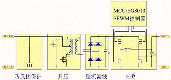
Application of PTC in Anti-Back Connection Protection Circuit
If the inverter does not have an anti-reverse circuit, it will often have catastrophic consequences when the input battery is reversed. It will burn the fuse and burn most of the circuit. There are mainly three kinds of anti-backconnection protection circuits in inverters: The anti-reverse protection circuit composed of anti-shunt Schottky diodes is shown in the following figure.
As can be seen from the figure, when the battery is reversed, the Schottky diode D is turned on and the F is burned. If followed by a push-pull main conversion circuit, the parasitic diodes of the two push-pull switch MOS transistors are also equivalent to parallel with D, but the voltage drop is much larger than the Schottky. The impact resistance of the transient current is also lower than that of the Schottky diode D, thus avoiding the high current passing through the parasitic diode of the MOS transistor, thereby protecting the two push-pull switch MOS transistors.
The anti-reverse protection circuit has a simple structure and does not affect efficiency. However, after protection, the fuse F will be burned out and needs to be replaced again to resume normal operation.
The anti-reverse protection circuit of the relay is adopted, and the basic circuit is as follows:

It can be seen from the figure that if the battery is reversed, D is reversed, no current flows through the coil of relay K, the contact cannot be closed, and the power supply of the inverter is cut off. This anti-reverse protection circuit has a better effect and does not burn the fuse F, but the volume is relatively large, and the life of the contacts of the relay is limited.
The anti-reverse protection circuit of the MOS tube is used, and the basic circuit is as follows:
In the figure, D is a parasitic diode for anti-reverse MOS, which is easy to draw and analyze. When the polarity of the battery is not reversed, D is positively turned on, and the GS pole of Q is turned forward by the positive electrode of the battery through F, R1, and D to return to the negative pole of the battery. The voltage drop after Q is turned on is much smaller than the voltage drop of D, so after Q is turned on, D will not get enough forward voltage and cut off;
When the battery polarity is reversed, D will be terminated due to reverse bias, and Q will also be terminated due to GS reverse bias, and the inverter will not start. This anti-reverse protection circuit has a long service life because it does not use a mechanical contact switch, and does not burn the fuse F like the anti-reverse protection circuit composed of an anti-transverse Schottky diode. The disadvantage is that the MOS has a certain loss when it is turned on. It is sufficiently unobstructed to maintain relatively low losses through relatively large currents.
As can be seen from the figure, when the battery is reversed, the Schottky diode D is turned on and the F is burned. If followed by a push-pull main conversion circuit, the parasitic diodes of the two push-pull switch MOS transistors are also equivalent to parallel with D, but the voltage drop is much larger than the Schottky. The impact resistance of the transient current is also lower than that of the Schottky diode D, thus avoiding the high current passing through the parasitic diode of the MOS transistor, thereby protecting the two push-pull switch MOS transistors.
The anti-reverse protection circuit has a simple structure and does not affect efficiency. However, after protection, the fuse F will be burned out and needs to be replaced again to resume normal operation.
The anti-reverse protection circuit of the relay is adopted, and the basic circuit is as follows:

It can be seen from the figure that if the battery is reversed, D is reversed, no current flows through the coil of relay K, the contact cannot be closed, and the power supply of the inverter is cut off. This anti-reverse protection circuit has a better effect and does not burn the fuse F, but the volume is relatively large, and the life of the contacts of the relay is limited.
The anti-reverse protection circuit of the MOS tube is used, and the basic circuit is as follows:
In the figure, D is a parasitic diode for anti-reverse MOS, which is easy to draw and analyze. When the polarity of the battery is not reversed, D is positively turned on, and the GS pole of Q is turned forward by the positive electrode of the battery through F, R1, and D to return to the negative pole of the battery. The voltage drop after Q is turned on is much smaller than the voltage drop of D, so after Q is turned on, D will not get enough forward voltage and cut off;
When the battery polarity is reversed, D will be terminated due to reverse bias, and Q will also be terminated due to GS reverse bias, and the inverter will not start. This anti-reverse protection circuit has a long service life because it does not use a mechanical contact switch, and does not burn the fuse F like the anti-reverse protection circuit composed of an anti-transverse Schottky diode. The disadvantage is that the MOS has a certain loss when it is turned on. It is sufficiently unobstructed to maintain relatively low losses through relatively large currents.


