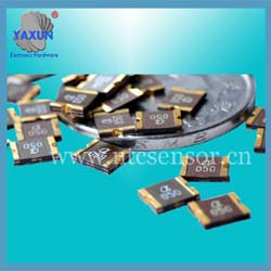
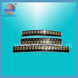
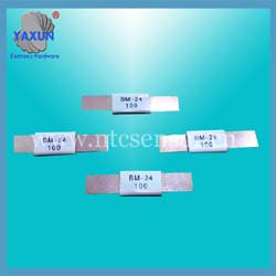
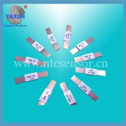
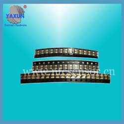
1210 SMD PPTC thermistor technology standard
- PRODUCT DETAIL
1.Rated zero power resistance
The PPTC thermistor should be packed according to the zero-power resistance, and the resistance value range should be marked on the outer packaging. After the withstand voltage and current resistance test, the resistance change rate of each sample in front of each group is extremely poor δ | Ri after -Ri before / Ri before-(Rj after -Rj before) / Rj before | ≤100%
2. PTC effect
Say a material has PTC (Positive Temperature Coefficient) effect. That is, the positive temperature coefficient effect only means that the resistance of this material will increase with increasing temperature. For example, most metal materials have a PTC effect. In these materials, the PTC effect appears as a linear increase in resistance with increasing temperature, which is commonly referred to as the linear PTC effect.
3. Non-linear PTC effect
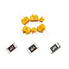
The phase-transformed material will show a phenomenon in which the resistance sharply increases by several to a dozen orders of magnitude along a narrow temperature range, that is, the nonlinear PTC effect. Quite a few types of conductive polymers exhibit this effect, such as high molecular PTC thermistors. These conductive polymers are very useful for making overcurrent protection devices.
4.Initial resistance Rmin
Before being installed in the circuit, the resistance value of the polymer PTC thermistor of the resettable fuse series is tested under the condition of an ambient temperature of 25 ° C.
5.Rmax
At room temperature, the maximum resistance value measured after one hour of self-resetting fuse series polymer PTC thermistor operation or reflow soldering in the circuit board.
6. Minimum resistance (Rmin) / maximum resistance (Rmax)
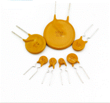
At the specified ambient temperature, for example: 25 ° C, the resistance value of the specific type of resettable fuse series polymer thermistor before installation in the circuit will be within a specified range. That is between the minimum (Rmin) and maximum (Rmax). This value is listed in the resistance column in the specification.
7, holding current Ihold
The holding current is the maximum current that can be passed by the resettable fuse series polymer PTC thermistor when it is not operating. Under limited environmental conditions, the device can remain indefinitely without transitioning from a low resistance state to a high resistance state.
8, the operation current Itrip
Under the limited environmental conditions, the minimum steady state current that causes the resettable fuse series polymer thermistor to operate within a limited time.
9. Maximum current Imax (withstand current value)
In the limited state, the maximum operating current of the resettable fuse series polymer PTC thermistor for safe operation, that is, the current resistance value of the thermistor. Above this value, the thermistor may be damaged and cannot be recovered. This value is listed in the flow resistance value of the specifications set forth in a column.
10. Leakage current Ires
The resettable fuse series polymer PTC thermistor locks in its high-impedance state when the current passes through the thermistor.
11.Maximum operating current / normal operating current
The maximum current flowing through the circuit under normal operating conditions. At the maximum ambient operating temperature of the circuit, the maintenance current of the resettable fuse series polymer PTC thermistor used to protect the circuit is generally larger than the operating current.
12, action
The process of resettable fuse series polymer PTC thermistor changes from low resistance to high resistance when overcurrent occurs or the ambient temperature increases.
13, action time
The time required from the start of overcurrent to the completion of the thermistor operation. For any specific resettable fuse series polymer PTC thermistor, the larger the current flowing through the circuit, or the higher the operating ambient temperature, the shorter the operating time.
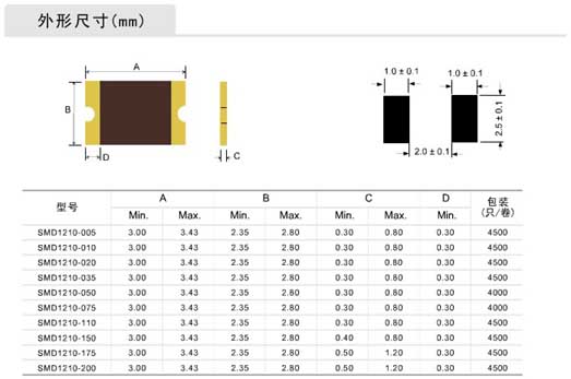
Performance specification (25℃)
The PPTC thermistor should be packed according to the zero-power resistance, and the resistance value range should be marked on the outer packaging. After the withstand voltage and current resistance test, the resistance change rate of each sample in front of each group is extremely poor δ | Ri after -Ri before / Ri before-(Rj after -Rj before) / Rj before | ≤100%
2. PTC effect
Say a material has PTC (Positive Temperature Coefficient) effect. That is, the positive temperature coefficient effect only means that the resistance of this material will increase with increasing temperature. For example, most metal materials have a PTC effect. In these materials, the PTC effect appears as a linear increase in resistance with increasing temperature, which is commonly referred to as the linear PTC effect.

3. Non-linear PTC effect
The phase-transformed material will show a phenomenon in which the resistance sharply increases by several to a dozen orders of magnitude along a narrow temperature range, that is, the nonlinear PTC effect. Quite a few types of conductive polymers exhibit this effect, such as high molecular PTC thermistors. These conductive polymers are very useful for making overcurrent protection devices.
4.Initial resistance Rmin
Before being installed in the circuit, the resistance value of the polymer PTC thermistor of the resettable fuse series is tested under the condition of an ambient temperature of 25 ° C.
5.Rmax
At room temperature, the maximum resistance value measured after one hour of self-resetting fuse series polymer PTC thermistor operation or reflow soldering in the circuit board.

6. Minimum resistance (Rmin) / maximum resistance (Rmax)
At the specified ambient temperature, for example: 25 ° C, the resistance value of the specific type of resettable fuse series polymer thermistor before installation in the circuit will be within a specified range. That is between the minimum (Rmin) and maximum (Rmax). This value is listed in the resistance column in the specification.
7, holding current Ihold
The holding current is the maximum current that can be passed by the resettable fuse series polymer PTC thermistor when it is not operating. Under limited environmental conditions, the device can remain indefinitely without transitioning from a low resistance state to a high resistance state.
8, the operation current Itrip
Under the limited environmental conditions, the minimum steady state current that causes the resettable fuse series polymer thermistor to operate within a limited time.
9. Maximum current Imax (withstand current value)
In the limited state, the maximum operating current of the resettable fuse series polymer PTC thermistor for safe operation, that is, the current resistance value of the thermistor. Above this value, the thermistor may be damaged and cannot be recovered. This value is listed in the flow resistance value of the specifications set forth in a column.
10. Leakage current Ires
The resettable fuse series polymer PTC thermistor locks in its high-impedance state when the current passes through the thermistor.
11.Maximum operating current / normal operating current
The maximum current flowing through the circuit under normal operating conditions. At the maximum ambient operating temperature of the circuit, the maintenance current of the resettable fuse series polymer PTC thermistor used to protect the circuit is generally larger than the operating current.
12, action
The process of resettable fuse series polymer PTC thermistor changes from low resistance to high resistance when overcurrent occurs or the ambient temperature increases.
13, action time
The time required from the start of overcurrent to the completion of the thermistor operation. For any specific resettable fuse series polymer PTC thermistor, the larger the current flowing through the circuit, or the higher the operating ambient temperature, the shorter the operating time.

Performance specification (25℃)
| Model型号 | Vmax | Imax | Ih | It | Pd | Time to trip | Resistance | ||
| V | A | A | A | W | Current(A) | Time(s) | Rmin(Ω) | R1max(Ω) | |
| SMD120P005TF | 60.0 | 10 | 0.05 | 0.15 | 0.8 | 0.25 | 1.50 | 4.000 | 50.00 |
| SMD120P010TF | 60.0 | 10 | 0.10 | 0.30 | 0.8 | 0.50 | 1.50 | 1.500 | 15.00 |
| SMD120P020TF | 16.0 | 20 | 0.20 | 0.40 | 0.8 | 8.0 | 0.02 | 0.400 | 5.000 |
| SMD120P035TF | 16.0 | 20 | 0.35 | 0.70 | 0.8 | 8.0 | 0.05 | 0.250 | 2.000 |
| SMD120P050TF | 13.2 | 40 | 0.50 | 1.00 | 0.8 | 8.0 | 0.10 | 0.200 | 1.200 |
| SMD120P075TF | 8.0 | 40 | 0.75 | 1.50 | 0.8 | 8.0 | 0.20 | 0.080 | 0.500 |
| SMD120P110TF | 6.0 | 40 | 1.10 | 2.20 | 0.8 | 8.0 | 0.30 | 0.050 | 0.260 |
| SMD120P150TF | 6.0 | 40 | 1.50 | 3.00 | 0.8 | 8.0 | 1.50 | 0.030 | 0.140 |
| SMD120P200TF | 6.0 | 40 | 2.00 | 4.00 | 0.8 | 8.0 | 2.00 | 0.030 | 0.100 |
| SMD120P260TF | 6.0 | 40 | 2.60 | 5.00 | 0.8 | 8.0 | 2.50 | 0.015 | 0.060 |
| Sign | Definition |
| Ih | Hold current-maximum current at which the device will not trip at 25℃ |
| It | Trip current-minimum current at which the device will always trip at 25℃ |
| Vmax | Maximum voltage at which the device will not trip |
| Vmaxi | Maximum voltage device can withstand without damage at it rated current |
| Imax | Maximum fault current device can withstand without damage at rated voltage |
| Rmin | Minimum device resistance at 25℃ prior to tripping |
| Rmax | Maximum device resistance at 25℃ prior to tripping |
| Figure | The Figure of PTC |
| Lead | Lead diameter |

