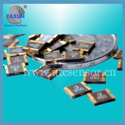
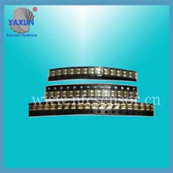
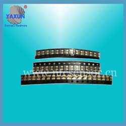
1206 PPTC SMD resettable Fuses parameters
- PRODUCT DETAIL
14, Vmax maximum voltage (withstand voltage value)
Under the limited conditions, the resettable fuse series polymer PTC thermistor can safely withstand the highest voltage when it operates. That is the withstand voltage value of the thermistor. Above this value, the thermistor may be broken down and cannot be recovered. This value is usually listed in the withstand voltage column in the specification.
15.Max working voltage
In the normal operation state, the maximum voltage across both ends of the PTC thermistor resettable fuse series polymer. In many circuits, this corresponds to the voltage of the power supply in the circuit.
16.Conductive polymers
Here refers to a polymer material made conductive particles (carbon black, carbon fibers, metal powders, metal oxides, etc.) of the insulating filling (polyolefin, epoxy, etc.) and the obtained conductive composite.
17.Ambient temperature
Temperature of still air around a thermistor or a circuit with a thermistor element.
18.Working temperature range
The ambient temperature range over which the P element can operate safely.
19.Maximum working environment temperature
The maximum ambient temperature at which the component is expected to operate safely.
20.Power loss
The power consumed by the resettable fuse series polymer PTC thermistor after operation is calculated by calculating the product of the leakage current flowing through the thermistor and the voltage across the thermistor.
21. High temperature and high humidity aging
At room temperature, measure the change of the resistance value of the resettable fuse series polymer PTC thermistor before and after it is in a relatively high temperature (such as 85 ° C) and high humidity (such as 85% humidity) for a long time (such as 150 hours).
22.Passive aging test
At room temperature, measure the change in resistance value of the resettable fuse series polymer PTC thermistor before and after it is in a higher temperature (such as 70 ° C or 85 ° C) for a long time (such as 1000 hours).
23.Hot and cold shock test
At room temperature, the test results of the change of the resistance value of the resettable fuse series polymer PTC thermistor before and after temperature cycling. (For example, cycle 10 times between -55 ° C and + 125 ° C).
24, PTC intensity β
PTC thermistors have sufficient PTC strength and must not exhibit NTC. β = lgR140 ° C / R room temperature ≥5 R140 ° C, R room temperature is the rated zero power resistance value at 140 ° C and room temperature.
25.Operating characteristics
The PTC thermistor should be tested for non-operation characteristics before and after the withstand voltage and current resistance tests, and R is the U / I at both ends of the thermistor when the non-operation characteristic test is performed. Rn is the initial or re-measured value of the rated zero power resistance.
26. Recovery time
The recovery time of the PTC thermistor should not be greater than 60S.
27.Failure mode test
During the failure mode test, the high-polymer PTC thermistor may accompany the test or be in a failure state. The allowed failure modes are open circuit or high resistance, but no low resistance or open flame should occur during the entire test.
Applications: All high-density circuit boards
Features: Surface mount components, faster than ordinary SMD fuse action
Operating current: 0.05A ~ 2A
Operating temperature range: -40 ℃ to 85 ℃
Lead-free, halogen-free environmentally friendly products, RoHS and REACH standards
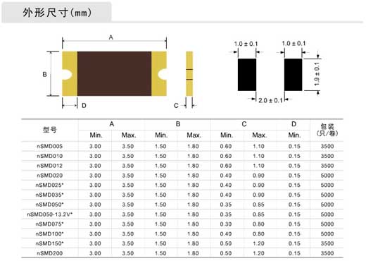
Performance specification (25℃)
Under the limited conditions, the resettable fuse series polymer PTC thermistor can safely withstand the highest voltage when it operates. That is the withstand voltage value of the thermistor. Above this value, the thermistor may be broken down and cannot be recovered. This value is usually listed in the withstand voltage column in the specification.
15.Max working voltage
In the normal operation state, the maximum voltage across both ends of the PTC thermistor resettable fuse series polymer. In many circuits, this corresponds to the voltage of the power supply in the circuit.
16.Conductive polymers
Here refers to a polymer material made conductive particles (carbon black, carbon fibers, metal powders, metal oxides, etc.) of the insulating filling (polyolefin, epoxy, etc.) and the obtained conductive composite.
17.Ambient temperature
Temperature of still air around a thermistor or a circuit with a thermistor element.
18.Working temperature range
The ambient temperature range over which the P element can operate safely.
19.Maximum working environment temperature
The maximum ambient temperature at which the component is expected to operate safely.
20.Power loss
The power consumed by the resettable fuse series polymer PTC thermistor after operation is calculated by calculating the product of the leakage current flowing through the thermistor and the voltage across the thermistor.
21. High temperature and high humidity aging
At room temperature, measure the change of the resistance value of the resettable fuse series polymer PTC thermistor before and after it is in a relatively high temperature (such as 85 ° C) and high humidity (such as 85% humidity) for a long time (such as 150 hours).
22.Passive aging test
At room temperature, measure the change in resistance value of the resettable fuse series polymer PTC thermistor before and after it is in a higher temperature (such as 70 ° C or 85 ° C) for a long time (such as 1000 hours).
23.Hot and cold shock test
At room temperature, the test results of the change of the resistance value of the resettable fuse series polymer PTC thermistor before and after temperature cycling. (For example, cycle 10 times between -55 ° C and + 125 ° C).
24, PTC intensity β
PTC thermistors have sufficient PTC strength and must not exhibit NTC. β = lgR140 ° C / R room temperature ≥5 R140 ° C, R room temperature is the rated zero power resistance value at 140 ° C and room temperature.
25.Operating characteristics
The PTC thermistor should be tested for non-operation characteristics before and after the withstand voltage and current resistance tests, and R is the U / I at both ends of the thermistor when the non-operation characteristic test is performed. Rn is the initial or re-measured value of the rated zero power resistance.
26. Recovery time
The recovery time of the PTC thermistor should not be greater than 60S.
27.Failure mode test
During the failure mode test, the high-polymer PTC thermistor may accompany the test or be in a failure state. The allowed failure modes are open circuit or high resistance, but no low resistance or open flame should occur during the entire test.
Applications: All high-density circuit boards
Features: Surface mount components, faster than ordinary SMD fuse action
Operating current: 0.05A ~ 2A
Operating temperature range: -40 ℃ to 85 ℃
Lead-free, halogen-free environmentally friendly products, RoHS and REACH standards

Performance specification (25℃)
| Model | Vmax | Imax | Ih | It | Pd | Time to trip | Resistance | ||
| V | A | A | A | W | Current(A) | Time(s) | Rmin(Ω) | R1max(Ω) | |
| SMD1206P005TF | 60.0 | 10 | 0.05 | 0.15 | 0.5 | 0.3 | 1.50 | 3.600 | 50.00 |
| SMD1206P010TF | 30.0 | 10 | 0.10 | 0.25 | 0.5 | 0.5 | 1.00 | 1.600 | 15.00 |
| SMD1206P020TF | 24.0 | 20 | 0.20 | 0.40 | 0.6 | 8.0 | 0.08 | 0.800 | 5.000 |
| SMD1206P025TF | 16.0 | 20 | 0.25 | 0.50 | 0.6 | 8.0 | 0.08 | 0.600 | 3.500 |
| SMD1206P035TF | 16.0 | 20 | 0.35 | 0.70 | 0.6 | 8.0 | 0.10 | 0.400 | 1.800 |
| SMD1206P050TF | 8.0 | 40 | 0.50 | 1.00 | 0.8 | 8.0 | 0.10 | 0.150 | 1.000 |
| SMD1206P050TF/13.2V | 13.2 | 40 | 0.50 | 1.00 | 0.8 | 8.0 | 0.10 | 0.150 | 1.000 |
| SMD1206P075TF | 6.0 | 40 | 0.75 | 1.50 | 0.8 | 8.0 | 0.20 | 0.090 | 0.500 |
| SMD1206P100TF | 6.0 | 40 | 1.00 | 2.00 | 0.8 | 8.0 | 0.30 | 0.060 | 0.250 |
| SMD1206P110TF | 6.0 | 40 | 1.10 | 2.20 | 0.8 | 8.0 | 0.30 | 0.055 | 0.240 |
| SMD1206P150TF | 6.0 | 40 | 1.50 | 3.00 | 0.8 | 8.0 | 1.00 | 0.030 | 0.150 |
| SMD1206P200TF | 6.0 | 40 | 2.00 | 3.50 | 1.0 | 8.0 | 1.50 | 0.018 | 0.110 |
| Sign | Definition |
| Ih | Hold current-maximum current at which the device will not trip at 25℃ |
| It | Trip current-minimum current at which the device will always trip at 25℃ |
| Vmax | Maximum voltage at which the device will not trip |
| Vmaxi | Maximum voltage device can withstand without damage at it rated current |
| Imax | Maximum fault current device can withstand without damage at rated voltage |
| Rmin | Minimum device resistance at 25℃ prior to tripping |
| Rmax | Maximum device resistance at 25℃ prior to tripping |
| Figure | The Figure of PTC |
| Lead | Lead diameter |

